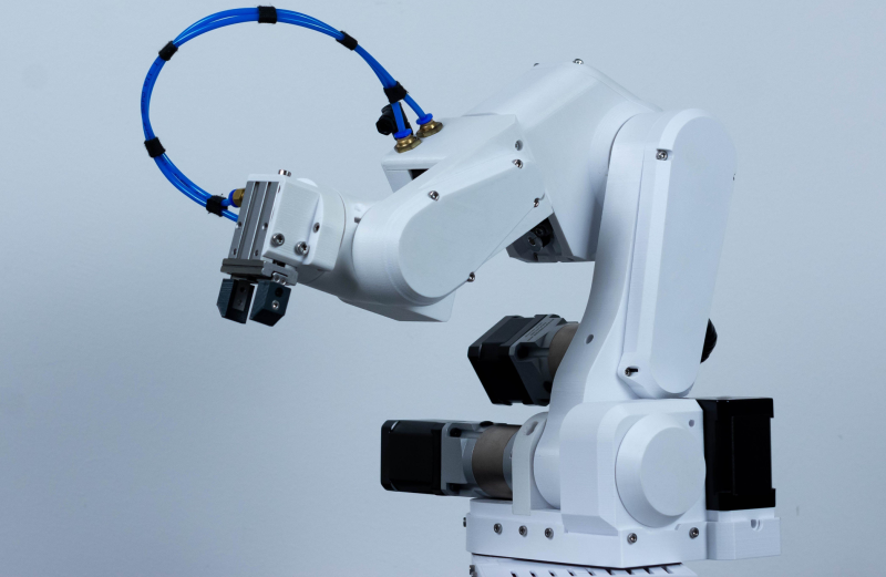
Parol 6 is a 3D-printed six-axis robot arm created by [Petar Crnjak] as a combination of the principles from a few previous projects. Aside from a pneumatic gripper, each axis is driven by a stepper motor, with at least a few of these axes being driven through a metal planetary gearbox for extra precision and torque.
From what we can glean from the work-in-progress documentation, there are some belt drives on four of the relevant axes and a mix of NEMA17 format steppers driving either 20:1 or 10:1 reduction boxes. There appears to be a mix of inductive sensors and traditional microswitches used, but it’s not so easy to work out where these are placed.
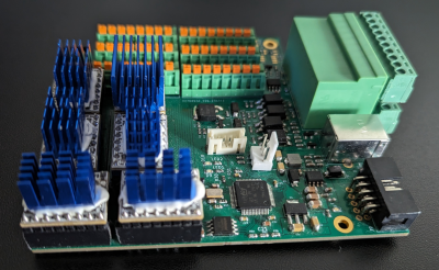
The controller PCB is a custom design based around the STM32F446 microcontroller, with modular drop-in boards for driving the motors, using the Trinamic TMC2209 for super smooth and quiet motion. The KiCAD project seems to be missing at the moment, with only gerbers and BoM for reference, but we expect that to appear at some point. There are some RS485 drivers on there, which is a sensible addition to providing an isolated interface if correctly implemented. There isn’t much detail on the electronics yet, but it all looks pretty standard fayre. The software stack looks like Arduino with a smattering of STM324xx HAL being used directly. The standard AccelStepper library is used, which is a good choice as it’s quite mature.
From the video logs in the project page, the robot looks complete, with some pretty good repeatability numbers, but we would like to see some data on absolute positioning accuracy as well, that said it’s a great project with an active Discord behind it, so let’s see how this develops.
We see a lot of robot arms, like this earlier Open Source design, but also this interesting hack straight out of the junk bin.


Open loop control and repeatability 🤡
Well, quite. It will look good repeatability-wise for a few experiments to prove the basic mechanics are good, but as you insinuate, long term repeatability without either closed-loop control or at least some other means of external calibration will be a challenge. Encoders should be easy to add in.
External calibration? You mean limit switches? Cheap AF limit switches?
I’ d like to see the device power cycled, then see how well it ‘repeats’.
I agree that for some serious repetability you need closed loop. That is why the project will be able to use closed loop FOC stepper drivers i am developing. PAROL6 design was made with that in mind, so you can easily stick drivers on top of the steppers. I will write a project about that soon.
If it can help, there’s this closed loop project for stepper motors. I’ve been running my 3d printer for years with these control boards+ magnets on motor axis. https://github.com/Misfittech/nano_stepper
Seems to me that repeatability in this case may be limited by stepper motor microstep size. Your resolution can’t get much better that step size and backlash control becomes critical. Making the same move multiple times does not prove accuracy in use because approaching the targets from different vectors induces different backlashes and different movement tolerances. Doing the same moves theoretically induces the same backlash and motion tolerances each time so you are really measuring motor position repeatability not repeatability of the entire robot. What matters in robotics is the ability to hit any arbitrary point within the workspace with a certain accuracy.
50micron repeatability is pretty solid for a stepper-motor driven arm of this size (though it’s likely a bit higher with a larger sample size).
Very true on the accuracy thing, and you’re dead on with the backlash thing. That can be mitigated in some applications with reasonable through being put into motion planning in design to allow the arm to have monodirectional approaches and rest on the same gearface, but sometimes those conditions just can’t be met. Making a robot accurate can be an endless rabbit-hole, with individual robot compensation, temperature compensation, etc, coming into play at times. And then you get into metrology, which is a whole other rabbit hole. How do you know that the robot is where your tools say it is? Laser trackers aren’t much more accurate than a few thou over a reasonably-sized arm’s envelope. Fact of the matter is that an accurate robot is much like a boat in that it’s a hole on the factory floor you shovel money into.
Something I’ve been seeing more and more is vision compensation, driving the arm where you think it should go, taking a look at the result, and dithering it in. It takes a lot of setup, adds cycle time, and has its own tolerance stackup (vision calibration plate tolerance, location of reference on robot, interpolation between calibration points) but as the field develops we’ll see more things like in-motion compensation, NN-assisted calibrations, etc.
I think the prize should be rescinded. It seems to be based on the understanding that the project is “a GPL desktop robotic arm”. While the software is GPL, the crucial control board is a proprietary, closed hardware design, as are the CAD files for the arm. The board can only be purchased from the project’s developer, at a cost of about $325, not including the stepper drivers. In the article above, it says “The KiCAD project seems to be missing at the moment, with only gerbers and BoM for reference, but we expect that to appear at some point.” But that never happened, and even the gerbers and BoM have now been removed. The developer says that there are no plans to make the control board open source.
Furthermore, the CAD source files for the printable parts are also not GPL or open source, and there is a license fee of about $50 for them. Only the printable STL files are open source, which are not easily modified. See issue #8 on their github page for the developer’s statement. I can understand the position that “the guy has to make some money”, but the project shouldn’t be promoted as GPL when core parts of it are not.