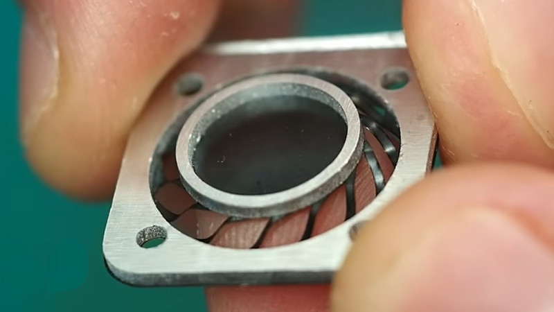
When we see something from [Carl Bugeja], we expect to see flexible PCBs and magnets being pushed to do unexpected things. His latest video in which he designs a set of PCB actuators using flexure joints certainly doesn’t fail to please.
His intent is to create a simple actuator in which a magnet is placed over a coil, and moves upward within the confines of he flexure which surrounds it. And rather than try individual designs one after the other he’s created a huge all-in-one test array of different flexure actuators, each having a slightly different design and construction to whichever one is next to it. There are plenty of magnet flips as he tests them, and using this approach he’s quickly able to eliminate the designs which work less well.
To give an idea how these actuators might be best used, he tried them in a few applications. Their lifting force is relatively tiny, but he found them possibly suitable for a haptic feedback device. Of particular interest is that as the structure is a PCB it’s relatively straightforward to run a line to the magnet and turn it into a touch sensor. The idea of an all in one sensor and haptic feedback component is rather appealing, we think.
If you’ve not seen Carl’s work before, we’ve encountered him many times over the years.


Ah. Reports that include information about the failures as well as the successes. Almost like … Science!
Very valuable and interesting. Keep it up!
Why use an expensive magnet when it’s possible to get motion from two opposing spiral electromagnets?
The force would be too weak. Think about it like this: force between two magnets is roughly (magnetic field 1) * (magnetic field 2). If you have two strong permanent magnets, force = (strong)*(strong) = very strong force. With a strong permanent magnet and a weak electromagnet, force = (strong)*(weak) = moderate force. If you have two weak electromagnets, force = (weak)*(weak) = very weak.
I wonder if flex-pcb can be wacum formed into a speaker cone..
Then you could make flex-pcb only induction speaker,
or maybe a more rigid and more powerful (with more coil layers) std-pcb and flex-pcb combo.
4 arms? I’d probably try it with 3 arms. 3 points define a plane. The magnet is a plane. You want linear vertical movement. I am assuming the springs are identical, which may not be the case. I’d try to characterize the repeatability of the springs with that manufacturing process.
So much talent, so badly applied. Almost all of those failures could have been foreseen by a tiny bit of thinking and *horror* some very basic engineering calculations. He made 40 parts and only 2 of them didn’t fail immediately. What a waste of time and materials. Seriously people, engineering involves maths. If you are making expensive parts without doing some maths first you have more money than sense.
And yet, he’s the one trying it and you’re the “expert” kvetching from the sidelines…
He gets all his made PCBs for free, and it makes for a better video to test a bunch of different ideas (yes, even the obviously flawed ones. The target audience is wider than just overly-parsimonious engineers). Engineering on camera has different requirements, including that you SHOW why something doesn’t work.
So I’d say, a lot of multi-domain talent, very precisely applied to balance the trade-off between good content and research. Don’t forget he uses his content to “fund” his experiments. And frankly, if you can’t see that, I wonder if you have done that tiny bit of thinking you’re so zealously advocating for.
I like his unique designs. I would like to have computer keyboard with these hoverin leaf like actuators. Maybe changeble tensions depending on Typo you use. Or in games the WASD Keys woobling depending the underground in the game. Or different feedback in photoshop, Excel and so on. Or the reptile skin from Mystique (X-Man Movie) when they fold over, so when you start your PC all Keys on your Keyboard mimic a wave.
didn’t force feedback keyboards already exist?