The RP2040 is a gorgeous little chip with a well-defined datasheet and a fantastic price tag. Two SDKs are even offered: one based on C and the other MicroPython. More experienced MCU wranglers will likely reach for the C variant, but Python does bring a certain speed when banging out a quick project or proof of concept. Perhaps that’s why [Jeremy Bentham] ported his RP2040-based vehicle speedometer to MicroPython.
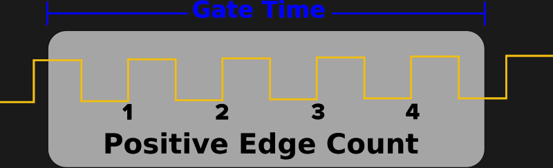
The two things that make that difficult are that MicroPython tries to be pretty generic, which means some hackery is needed to talk to the low-level hardware, and that MicroPython doesn’t have a reputation for accurate cycle counting. In this case, the low-level hardware is the PWM peripheral. He details the underlying mechanism in more detail in the C version. On the RP2040, the PWM module can count pulse edges on an input. However, you must start and stop it accurately to calculate the amount of time captured. From there, it’s just edges divided by time. For this, the DMA system is pulled in. A DMA request can be triggered once the PWM counter rolls over. The other PWM channel acts as a timer, and when the timer expires, the DMA request turns off the counter. This works great for fast signals but is inaccurate for slow signals (below 1kHz). So, a reciprocal or time-interval system is included, where the time between edges is captured instead of counting the number of edges in a period,
What’s interesting here is how the hardware details are wrapped neatly into pico_devices.py. The uctypes module from MicroPython allows access to MMIO devices such as DMA and PWM. The code is available on GitHub. Of course, [Jeremy] is no stranger to hacking around on the RP2040, as he has previously rolled his own WiFi driver for the Pico W.


To get the best of both worlds (pulse counting and edge counting), you can capture both the number of edges and their timestamps. Then for every time you want an update of the frequency, divide the number of captured edges by the exact time between those edges. This gives good accuracy at any frequency of input signal, and it is also straightforward to cope with the case where input frequency is lower than update frequency.
Implementation for RP2040 left as an exercise to the reader :)
I used to think CircuitPython might be the future, but then I saw ESPHome. It’s both higher level and more performant, the only thing it doesn’t have is runtime executing apps from an SD card.
Really impressive project, to me almost as revolutionary as Arduino.
What am I missing here? Using DMA is a rather complicated way to emulate a simple external AND gate.
So you do something accurate in uPython by writing a C program and putting a wrapper around it, and this is supposed to be easier to develop then just C / C++?
I also wrote some software for a reciprocal frequency counter ( some 15 – odd years ago) I think I used two timers. One was counting at the mains CPU frequency, and the other was counting the input signal, and using a prescaler to divide it’s frequency to get into the range of a decent “gate time”. So this is pretty much the same as jpa posted here earlier. A simple calculation: If you want to measure a frequency with a 10ppm resolution with a reciprocal counter, then you need to accumulate at least 1e5 pulses of the fast clock, and if your uC runs at 20MHz, then you need to derive a “gate time” of more then 1e5/2e7 = 5ms. Accumulating the main CPU clock over a longer time gets more resolution, but you also have to capture it cycle accurate in comparison with the clock signal you want to measure, and this is best done with hardware. I did it with an Atmega8 (long before arduino existed) and it did not have very advanced hardware, so I had to rely on a 3 cpu cyle software loop for the critical section and this reduced the accuracy a bit. I am not sure how to overcome this with DMA DMA is still started and stopped by software. An STM32 can probably do this easy by connecting two timers together, and then one timer captures it’s count when another timer overflows. And you keep on capturing overflows until you have accumulated enough resolution in the “fast” timer.
Another trick is to not “start” and “stop” any of the peripherals. You have both free running on their clock signal and capture the state of the fast clock when the slow clock overflows. This adds a few lines of software because you have to do a substraction to get the difference in clock pulses before you can do the division, but omitting all the starting and stopping of the peripherals also simplifies the software.
But the important thing here is two fold. First, you have to rely on hardware as much as possible (Adding a logic gate to get the timing cycle accurate can help.) Second, there are several different ways to get to an accurate result, and you have to read the datasheets of your favorite microcontroller and think a bit on how to combine the available peripherals efficiently. And third, you are going to need some register level programming, with just “arduino level” knowledge and tactics you are not going to get the best results.
===========
In a variant on this, you can measure drift between to oscillators (for example 10MHz reference clocks GPSDO and OCXO) in a very similar way. You just keep accumulating data without ever stopping the peripherals and the data from the capture / compare register will have slow deviations over time as the clocks drift.
Yes, it’s very common to implement a small amount of C/C++ and wrap it so it’s accessible from MicroPython. And yes, it usually turns out to be *much* easier to do this than write the whole applications in C.
well, you could have used an esp32 and C and done the whole thing in about 5 minutes. Why anyone wants to use python on these chips is beyond me…
Or even a 328P with C – another 5 minutes…
Because Python is a much more accessible language (I make no comment on the difficulty of the language, but the amount of online resources is so much higher and it’s the default for more and more computer science classes).
Why haven’t you mentioned C on this particular chip (RP2040)? It has *extremely* well known and used architecture and core (Cortex M0+) and tooling and hardware debuggers instead of ESP’s Chinese weird one. And guess what. RP2040 is cheaper, even the module with wifi/bluetooth.
Same reason people put JavaScript on the server.
It’s the only language they know.
That IS the ‘kind’ interpretation.
The unkind one is ‘they are blithering morons’.
Javascript in the server is fantastic, especially for a more advanced programmer. Would help if you understood the Lisp / Scheme / Smalltalk / Self / V8 evolution – which few do.
However, in this case, very much wondering if C might be more suited to an RP2040.
Imagine a microcontroller without general purpose timers and fanboys lovin’ it.
RP2040 sucks it’s got ONE 64-bit timer for doing SysTicks just like needed by an OS that it doesn’t really have.
Too bad, I think the IC was designed by people with little experience in embedded applications.
It wasn’t really designed for a classical embedded role. It’s more aimed to be a flexible low-cost introduction to hardware manipulation, with enough capability for actual hobbyist use rather than pure-classroom education.
If you’re familiar with embedded development, there are many other choices. But there are people who have simpler projects and lack the need (or time) to climb the required tower of babel to familiarize themselves with more complicated hardware.
It’s notable how many fun projects are out there, where even a RP2040 is overkill….
Hard disagree – they took the opportunity to do something new without being hamstrung by design decisions made decades ago, and the result is incredibly good.
The RP2040 is *insanely* powerful relative to other microcontrollers of similar clock speed. You have to do things differently, but it opens up huge new possibilities, while still being brilliantly accessible to a newcomer.
My current project can be handled by an RP2040 but would otherwise be completely impossible without a 800MHz M7 at a minimum. There is very little that can’t be done on it that other chips can do, and the answer to “why did they leave the timers out” is “because they’re *redundant*”.
There are 12 DMA channels, pacing timer, all the PWMs can be used as timers as well and PIOs have clock dividers. Everything produces interrupts and DMAs can be chained to execute complex transfer scripts without CPU involvement. I have never felt the need to use a timer with higher than 1ms precision.