There are too many different kinds of displays – some of them, you already know. I’d like to help you navigate the hobbyist-accessible display world – let’s take a journey together, technology by technology, get a high-level overview of everything you could want to know about it, and learn all the details you never knew you needed to know. In the end, I’d like you to be able to find the best displays for any project you might have in mind, whatever it could be.
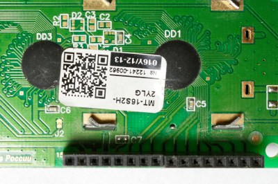
Today, let’s take a look at a well-known LCD technology – the HD44780 displays, a type of display that we hobbyists have been working with since the 1980s. Its name comes from the HD44780 driver chip – a character display driver IC that connects to a raw display panel and provides an easy interface.
HD44780 displays are not known for power efficiency, cutting-edge technology, ultimate flexibility, or small size, for that matter. However, they’re tried and true, easy to drive, require little to no computing power on your MCU, and you will be able to buy them for the foreseeable future. They’re not about to get taken off the market, and they deserve a certain kind of place in our parts boxes, too.
If you work with HD44780 displays for a project or two, you might acquire a new useless superpower – noticing just how many HD44780 displays are still in use in all sorts of user-facing devices, public or private. Going out and about in your day-to-day life, you can encounter a familiar 16 x 2 grid of characters in cash registers, public transport ticket machines, home security panels, industrial and factory equipment, public coffee machines, and other microcontroller-assisted places of all kinds!
Ease Of Use
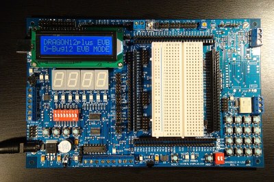
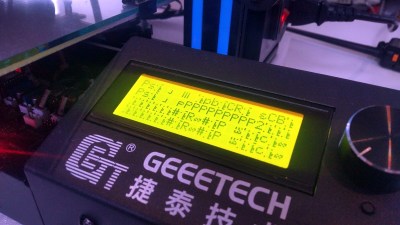
You really can’t go wrong with a HD44780 display if all you want is some basic text output. We’ve been using them as displays for all sorts of projects, 3D printer UI screens, home server status indicators, robot and other gadget diagnostics, clocks, spectrum analyzers. It used to be that any MCU development board you could buy, would have a HD44780 display on it, or at least a header for it!
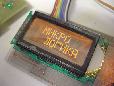
As you might guess, the HD44780 IC is hardwired to show characters – you can’t switch arbitrary pixels on a HD44780 display, all you can do is ASCII, oh, and up to eight custom characters you can upload. The display sizes are also standardized – 16×2 is the main one (also searchable as 1602), but you can also get 20×2, 16×4 and 20×4 displays, as well as 8×1 and 8×2 (2002, 1602, 2004, 0801 and 0802 accordingly).
These are characters, of course, not pixels – not that you can control individual pixels, anyway. Sometimes, you can find even wackier displays, like 40×2, 40×4 or even larger – those might use slightly modified controller chips, or even multiple HD44780 on the same board working together and wired up to the same pin header.
Connections
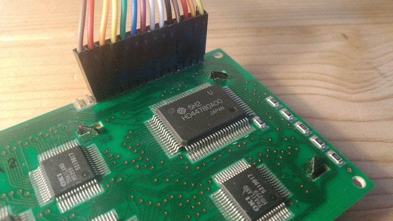
Speaking of pin headers, the overwhelming majority these displays have a standardized pinout on a line of 0.1 in / 2.54 mm headers, easy to breadboard or connect to a development board – just 14 pins, or 16 if your HD44780 panel has a backlight. These are still LCDs, after all, and you’ll want them to be backlit. Adafruit has also sold RGB backlit HD44780 displays in the past, you know, in case you’re designing gaming peripherals.
Sometimes, the pin headers are different – 8 x 1 and 8 x 2 displays use the same pinout but transferred onto a 2 x 8 pin header instead. Want to use one of those I2C boards with a 8 x 1 or 8 x 2 display? Here’s an adapter PCB. And, if you have a super wide HD44780 display, it will likely use multiple controller chips, and as a result, it’s probably going to be a dual-row pin header with a more special pinout that has multiple E pins, one per each HD44780-compatible controller it would have onboard
For all these pins, a typical HD44780 display only needs six GPIOs – don’t let the eight data pins fool you! This is because HD44780 displays have two modes you can use to send data, 4-bit mode and 8-bit mode. Nobody uses the 8-bit mode. To be exact, there’s no benefit to using 8-bit mode unless you want to update your display really really quickly, or absolutely guarantee error-free operation! In 4-bit mode, you only need to use pins D4-D7, feel free to leave D0-D3 floating or pull them down to GND. The other two GPIOs go to E and RS inputs – there’s also R/W, which you usually set low, but you can also set high to read data from the display! Nobody uses the read feature. Well, again, you can use it to guarantee quick updates and no-error operation by checking that the display has completed your command before sending the next one, but nobody does that and the displays work just fine!
Contrast
A typical HD44780 display module tends to have a quirk – it has a single analog input you must use. This is the Vo input, a pin for contrast voltage for the LCD panel itself, and it differs from LCD to LCD – remember, even if all we’re doing ASCII, HD44780 is old enough that you’ll see the bare metal shine here and there.
Oh, VCC, right. These displays tend to work at 5 V as their main voltage – again, the HD44780 was designed in 1980s, so you typically need to have a 5 V source in your project if you want to use one of these. But 3.3 V GPIOs are okay! There are displays that work with 3.3 V VCC, but they’re rare. The main problem isn’t the HD44780, though – it’s the Vo, it’s referenced to VCC instead of GND, so if you need to set Vo to 1V when using 5 V VCC, you’ll need to have it at -0.7 V for 3.3 V VCC. Thankfully, there’s a solution, and you might have already noticed that some HD44780 displays have a SO8 footprint on the back! They’re never ever populated, but you can populate them with an ICL7660 or similar chip to create negative Vo, and get your HD44780 display to work at 3.3 V VCC! Some displays will need negative Vo even without 5 V. I’ve once disassembled a payphone that used a custom HD44780 display, and if I remember correctly, it used -2 V for Vo by default! It makes sense – Vo varies with temperature, and those payphones were built to be weatherproof.
Software Support Abundant
One place where HD44780 displays shine is the sheer amount of software support – interfacing with a HD44780 display is something you really don’t have to give much thought, as it stands. There is hardly a platform you can find, that doesn’t already have a HD44780 library someone wrote for it; whatever language you’re coding in, chances are, there’s a snippet of code that implements the HD44780 command set and is just waiting for you to download it.
Even on Linux, the LCDProc software works with a wide variety of ways you can connect a HD44780 display to your system, and a good amount of UIs you can use to monitor your system’s state. We’ve had HD44780 displays for almost four decades now, and for good reasons.
HD44780 isn’t the best option in many cases. For instance, you will hardly see a modern devboard with HD44780 support nowadays – they’re somewhat bulky, so manufacturers opt to use lightweight and small SPI and OLED screens that are hardly less expensive. That said, HD44780 have a well-deserved place in our toolboxes, and next time you want to simply display a few lines of clearly readable text without giving the UI and fonts much thought, you should absolutely reach for a time-tested character display, plug an I2C backpack onto its back, and save yourself the effort and pins of anything higher-fidelity. Next time, however, we’ll take a look at other options we can reach for in cases the HD44780 literally outweighs its usefulness.



I have here perhaps seven such displays that use it. Three are from Parallax. One is from Sparkfun and includes a configured PIC to do translations from serial their way, and the Parallax ones are setup in similar fashion. And some displays that are not populated with pins. I think those are all of four items.
yes, the interfaces that offload the HD44780 commands even further are pretty cool! using an I2C GPIO expander can sure be pretty wasteful – you need three I2C writes just to send a nibble to the display.
I love these character displays. Usually do what’s needed if you don’t need color or graphics and easy for even a non-software guy like myself. I keep a few I2C to parallel converters on hand for when I need I2C for display comms.
I love this simulator – it really helped me understand how it works:
http://www.dinceraydin.com/djlcdsim/djlcdsim.html
Cool looking simulator, just a shame the instructions for using it are stuck in a Flash video.
oh that looks wonderful, thank you!
In the early 90s, I made a graphic mouse cursor on it, using 4 characters dynamically refreshed in CGRAM.
It makes me want to do it again!
I love these displays. I used them a lot with my homebrew CPU projects. And “Nobody uses the 8-bit mode”? Really? I use the 8-bit mode to speed things up a bit on my transistor computer. I have programmed a “Breakout” game and a few others that use the user definable characters, and when the bitmaps in the display are updated quickly, the HD44780 display looks like a dot matrix display. Please see the demos in this video, starting at 2:32:
https://www.youtube.com/watch?v=VgktjP_Fcy8
I have been looking for a display to go with a keyboard, in a style similar the the HP15C calculator.
These show promise, but I’d prefer something the full width of a keyboard.
a combination of display and keys could be a collaboration, with Keebin’ Kristina.
>To be exact, there’s no benefit to using 8-bit mode unless you want to update your display really really quickly, or absolutely guarantee error-free operation!
Or you have a bus-based system, like 8051, [jk]but who uses them now, anyway?[/jk] You could have a whole bunch of displays stringed on a single bus alongside the other peripherals and with a properly designed hardware you would only need an address and a single-ish MOVX.
Aside from that, here’s a couple of tips on repairing the old ones. There’s a few resistors usually on the backside of the display module, so
– if it doesn’t display anything and just scans the screen with variable speed, then it’s a 91kOhm one;
– if it has weird uneven contrast from column to column (depends on the character displayed) or it is simply flooded full with characters barely visible, and adjusting Vo doesn’t work right, then it’s the string of four or five resistors of the same value in the kOhm range (2k2, 4k7 or so).
What would I have to adjust these resistors to in order to get the display pcb to output near logic +5V on the display section? Reason I’m asking is that I’m trying to replace the LCD with a 16 character 5×8 x 2 line LED matrix and need to drive some ULN2003s with the 44780. Ie, I’m trying to build an led display that uses the hd44780.
I know it can be done, as someone did it back in 1996, but I can’t get into contact with them as their website email is full.
Nowadays I use the I2C backpack as the article mentions, but in the past I’ve wired it up and wrote the code in AVR assembly to make it work. One thing I learned in writing that, is that there is a “second screen” off to the side. So you can upload two full 16×2 screens into the display’s RAM, and then switch between them with a single command.
They’re also available with RS-232 or USB interface from companies such as CrystalFontz.
Some of my displays have an “extended temperature range” and these need a negative voltage on the contrast pin. About -3V or so.
A classic way to generate this was to use something like 74HC14 hex schmitt trigger inverter, build an oscillator, use some of the inverter gates in parallel as an output driver and a few diodes to complete the charge pump. The current draw on this negative voltage is tiny.
On Linux, there is no longer a need to use userspace libraries like LCDProc. Linux has its own HD44780 charlcd driver. Just describe the wiring in DT (Device Tree), with or without a deserializer, and enjoy /dev/lcd!
https://elixir.bootlin.com/linux/latest/source/Documentation/devicetree/bindings/auxdisplay/hit,hd44780.yaml
ohhh that’s pretty lovely, I should check that out! thank you!
Unfortunately, doesn’t seem to support serialized connections, so it would not have been useful for half of the projects I used it.
For displays taking the commands directly from i2c, there is
https://elixir.bootlin.com/linux/latest/source/drivers/auxdisplay/lcd2s.c
I guess it can easily be extended with UART support.
‘44780s are prone to locking up. Possibly from static to the display, or perhaps (being a 4 bit micro inside) they can lock up, and cannot be written to anymore. (If you are paying attention, you will notice this on various public facing text lcds)
You should always include a power switch transistor, and periodically restart them in long running applications.
Maybe only certain models of them, because I still have to encounter the issue among the literal hundreds of 1602s I closely see every year, even with the most of them having over a decade of uptime and not a small part of them closing their second decade in a two year straight runs.
Most of them is SC1602B. And they still serve well except for the cases when some positions on the screen begin to flip from the intended character to some certain other one. And that happens not instantly on power-ups but with time (minutes to days) and device’s warming-up. It looks as if a certain bit of a character’s address in CGROM flips randomly. Replacement helps.
Why haven’t SMART people showed us how to reprogram these with custom characters. There are 40 plus blank spaces in memory that could be filled. This can’t be that hard
Because only 8 of the positions are in RAM? The rest is in ROM. You can order the chip with custom characters put into mask ROM.
i know all that… i would like to fill the rom with my own characters. to order a custom char set is expensive and they must be able to load a new set onto the rom. why hasent someone allowed me to download the rom and modify it and but my new data back. this cant be that hard especially that we all have programmers now.
ROM… You cannot write to ROM. Contents of ROM have to be set during production.
So, no “i would like to fill the ROM…”
Only manufacturer can do this in masking-step.
“download the rom and modify it and but my new data back. this cant be that hard especially that we all have programmers now.”
no. No you cannot write it back. it is ROM. Read Only Memory.
What you think about is PROM (Single user-programmable Rom), EPROM (Normally UV erasable ROM) and EEPROM (Electronically Erasable Programmable Read Only Memory.
EEPROM can be written by those programmers. ROM is the same as if you wanted to change what the Controller does and “erase” its capabilities and flash a new Firmware to it. Not possible as the “Program” is etched in silicone and not changeable. Same as the ROM.
If you want something a bit more nice to look at, you can even get OLED or VF-Displays with HD44780-compatible interfaces that are true drop-in replacements.
Do you have a part number for the VFD version? That would be lovely to look at.
I’ve had one collecting dust for years, until recently. I bought an I2C adapter and I’m now using it as a debug monitor for various projects. It’s really handy, much more than serial debug, in many instances.
A couple of years ago I managed to get a decomissioned payphone from our telco, and it’s hella interesting inside. Runs on a 68000 and uses one of these 16×2 displays. :)
Thankyou Arya for the article, it inspired some very useful ino in the comments section too! I’m looking forward to the rest of the series… This IS a series, right?
*useful inFo. Stupid phone “keyboard.”