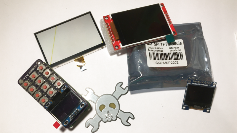
I’ve talked about HD44780 displays before – they’ve been a mainstay of microcontroller projects for literal decades. In the modern hobbyist world, there’s an elephant in the room – the sheer variety of I2C and SPI displays you can buy. They’re all so different, some are LCD and some are OLED, some have a touchscreen layer and some don’t, some come on breakouts and some are a bare panel. No matter which one you pick, there are things you deserve to know.
These displays are exceptionally microcontroller-friendly, they require hardly any GPIOs, or none extra if you already use I2C. They’re also unbelievably cheap, and so tiny that you can comfortably add one even if you’re hurting for space. Sure, they require more RAM and a more sophisticated software library than HD44780, but with modern microcontrollers, this is no problem at all. As a result, you will see them in almost every project under the sun.
What do you need for those? What are the requirements to operate one? What kind of tricks can you use with them? Let’s go through the main aspects.
The Basics
 These displays are all fundamentally the same in how you create the data to be displayed. There’s no interface to show text strings anymore like there is with HD44780 displays – you take control of pixels, monochrome or color, and you have to send them to the display from your microcontroller. This means you have to have enough RAM to represent all those pixels, or generate them on the fly naturally, which puts a cap on the kinds of MCUs you can use.
It’s possible to send partial updates to such a display, so that you can create UI by sending different chunks of data to different regions of the display. For instance, I’ve once built an UI that solely did partial updates for a 320 x 480 color display driven by an ESP32, in a project where RAM was already at a premium. To help with such tasks, many displays allow you to read pixel data out of them. However, it will require more intricate code, so a typical library allocates a full screen’s worth of space for the display and calls it a day.
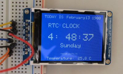
There are two interfaces typically used for these displays – I2C and SPI. I2C is easier and is likely already available in your project, but it puts a cap on your data transfer speed. This means that you will hardly ever see a color display with an I2C interface – because, as a rule, you need to send 16 times more data to update a color display as opposed to a monochrome one, for the same amount of pixels. You can push SPI faster – whereas I2C typically goes either 100 kHz or 400 kHz, rarely 1 MHz, you can typically push data into an SPI display at a few MHz clock rate, often even 10 MHz.
If you’ve miswired an SPI display, you will get no output and no idea on what’s going on, until you re-inspect your wiring and code, thoroughly look the problem up online, or plug a logic analyzer in. It’s not like miswiring SPI displays is all that easy, but it’s not uncommon when doing bringup on unfamiliar displays, and it can happen to anyone. Also, the extra SPI pins require extra GPIOs, and it’s not uncommon that you can’t share the SPI bus with other displays unless you add a 74×125 gate to make sure that your SPI display is not interfering with other devices on the bus.
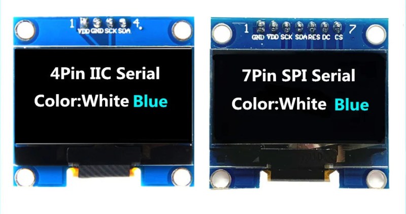
These factors are not a problem as such, they’re merely things I describe so that you know which display to pick in which situation. If you’re starting out in electronics and you’re fine with monochrome output, pick up an I2C OLED, they’re numerous and software support is omnipresent. If you want high speed updates or color output, you’ll have to work with an SPI display. By the way, displays like SSD1306 and SH1106 OLEDs support both I2C and SPI – it depends on how the breakout is wired up; TFT displays only support SPI as a rule. Picked one of the two, and found the GPIOs needed? Let’s talk software.
A Little Code
If you want to know how a system works, it’s helpful to see how it breaks – so let’s describe possible (but rare) software incompatibilities and see where they come from. I’ll discuss wiring problems in a later section, for now, let’s assume you have a working link with the display and all GPIOs are in order. First thing to look into, then, is the controller IC type. Every LCD or OLED screen has an IC bonded to the panel – it’s the square pretty piece of silicon, that is often covered with a black sticker to protect the silicon from stray photons and general damage. There’s different families and models of these ICs, and they’re a defining feature for a typical screen – when picking a library, it’s important to know which screen controller it’s for.
Different controllers might require different SPI modes, control pins or clock speeds. However, most often, what’s different is the ‘language’ that the controller uses – its registers and their addresses, the values you need to write into these addresses, and the way it accepts screen data. If you port a library from one controller to another, you might need to change the way that the library speaks to the controller in general, learning it from a working library for your controller in a different language. If controllers are similar, say, ST7789 vs ST7789V, they’ll often speak the same fundamental language, and you might only need to change a few register values in the initialization sequence.
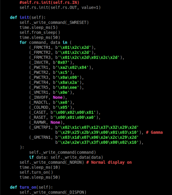 Initialization sequence is a sequence of register writes that you have to send to your display before you can show any data on it, and it is often the key for fixing display problems. For instance, if you have a certain controller display and a library only supports that controller with a different resolution panel connected to it, what you’d need to change is the bytes in initialization sequence responsible for controller-to-panel wiring mapping. Sometimes the resolution is the same, but the pixels are wired slightly differently, and that also fixable in the initialization sequence.
The initialization sequence is also where you can rotate or flip a display ‘in hardware’, in case your project needs the display to be in a certain non-default orientation – find a value to change, and the display will map the pixels in a different way. A single controller IC could work with a myriad, which is why, even if you find a datasheet for the display controller IC, it might not help you when you need to make your actual display work, because the controller datasheet might not have the exact initialization parameters you need to know.
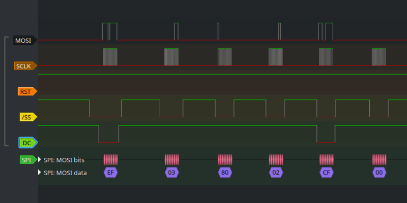
If you can’t find the proper initialization sequence or it’s hard to introspect the code, you can always sniff it with a logic analyzer! It can also help you figure out things like different commands to write pixels to the display – sending data to the display also has to be preceded by a certain command sequence, which has you give the display the address of the place you want to push the pixels into. Those commands are somewhat standardized by MIPI Alliance, so there’s only a few common ones and they don’t tend to change for the same display manufacturer, but it’s a good thing to keep in mind depending on how much you need to adapt your library.
This is about what you need to know when it comes to display software. Chances are, you’ll never have any problems on this front, but now you know where to look if you do. Let’s descend to more earthly matters – wiring.
A Little Wiring
The overwhelming majority of SPI and I2C displays expect 3.3 V VCC. Make sure to not reverse GND and VCC – if you do, your display’s controller IC will die. Also, many display breakouts include a 3.3 V linear regulator on them, so that people can power them from 5 V too – it’s not exactly needed, but it can be nice to have. Other than that, for LCD panels, you will need to manage the backlight. You can typically hardwire it to VCC and GND – a resistor shouldn’t be needed, as it’s usually included on the breakout PCB. If you want manual backlight control, an N-FET or an NPN transistor will make quick work of that if it’s low-side (GND-side) control, P-FET or PNP for high-side (VCC-side) control, and, of course, you can PWM it!
 SPI and I2C displays differ in their wiring. I2C displays rarely ever need anything other than SDA and SCL. Here’s one exception though, and that is the RST signal, something that both I2C and SPI displays tend to need. Everywhere I’ve seen it, it’s a non-negotiable signal – after the display gets powered up, you need to ground RST for a bit before you even dare to send data. If your display breakout has RST exposed and you ignore it, you’re setting yourself up for a bad time.
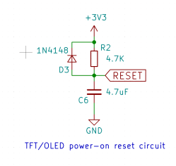
However, that doesn’t mean you need to waste a GPIO on a signal that only changes once! As a rule, a simple resistor-capacitor circuit is sufficient to toggle the display’s RST pin right after power-up, and many breakouts include this circuit by default, with an extra diode to make sure that even the quickest power dips still result in a display reset. The capacitor has to be in single-digit uF range, but that’s not much of a problem to source, it doesn’t have to have a super good temperature coefficient or high maximum voltage or anything. Here we go, that’s one more spare GPIO for your project use!
SPI displays also need CS, naturally. Some displays perma-ground CS and never expose it to the user, which takes the SPI bus hostage and is all-around annoying to work with. If you want to ground CS and not waste a GPIO on it, you always do it out of your own volition! Some displays won’t like a perma-grounded CS, as they use the CS signal for internal purposes and expect you to switch it as you send data, but, for instance, typical SH1106 OLEDs sure don’t seem to mind.
Another signal that exclusively SPI displays need is D/C, also known as A0. This signal tells the display whether you’re currently sending data or commands to it – since displays operate in 8-bit mode and you have to use the whole 8 bits for your commands or data bytes, you need some sort of sideband to tell the display which one it’s receiving at any given moment. If you want to omit this pin, you can either send data to the display in 9-bit SPI mode instead of the default 8-bit mode, something that your MCU often won’t support, or do a witty workaround! Oh, and for panels capable of both SPI and I2C mode, this signal might be used for the LSB of the I2C address when the panel is wired up for I2C mode, so that you can theoretically have two of the same displays on the same bus. If you need more than two of these displays, add more I2C buses, or use I2C address translators.
A Little Hacking
Display breakout boards are amazing and they’re what you will use in the majority of case – you can use them easily on your custom boards too, just put a 4-pin header on the board and plug a display breakout into it. However, breakouts shall not constrain you. If you want to build a smaller device, you can always put the bare panel on your board – you need the FPC footprint and mechanical considerations for the bare panel, but that’s it. Make sure you really really have the correct pitch for the display FPC connector – lifting it from open-source KiCad projects is your best bet, and a datasheet for the panel (not the controller IC!) will help too. It’s really annoying to produce a board that – print the board out on paper if you must.
Many OLED displays want charge caps – find breakout schematics online and repeat them, and if you can’t find schematics, re-draw the breakout you have and measure the caps with a capacitance meter. Some LCD panels require an external boost circuit, especially color OLEDs and some small TFTs – there’s some open-source projects to learn from if you want to work with a panel that has such a requirement.
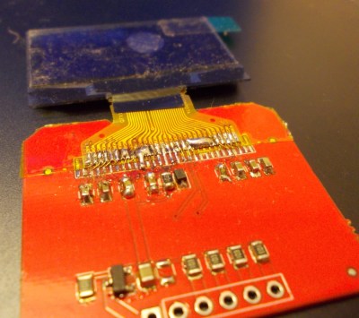
When you need to unglue a display panel from its breakout for whatever purposes, reverse-engineering or repair alike, mind you that it’s typically glued to the PCB with double-sided tape. Use a hairdryer to heat up the tape from the PCB side (not the screen glass side!) and then use a plastic spudger to lift it equally from all sides, a credit card could work wonders too. Be very, very careful and measured while applying force, don’t shatter the LCD/OLED glass, and don’t tear the FPC! If you’re working on one of the OLED screens that fold over a board, desoldering the FPC first might help – then you can rotate the panel, which should help free up the display from the tape a fair bit faster, just be careful gripping it. Isopropyl alcohol might be tempting to use, but beware – it might damage the polarizer layer on the panel, heat from a hairdryer is what I’ve found works best. A hot air gun at soldering temps is likely to cause the SMD parts on the other side of the breakout to shift by accident, but if you don’t have any to worry about, that could work in a pinch too!
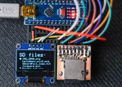
A lot of the common OLED and LCD displays have Linux kernel drivers! With the right modprobe command or a DeviceTree snippet, you’ll be surprised to see the Linux boot logs and then a `tty` prompt appear on your tiny screen. You can’t quite send arbitrary commands or tweak the initialization sequence easily while using a Linux driver, but it’s all open-source, so there’s some ways around it.
 That about sums up what you should know about the most common type of display you can encounter. With the basic things out of the way, you should be able to get to whatever goal you need this display for, instead of spending time debugging common problems. The displays themselves are fascinating, too – just a few months ago, on Hackaday Discord, we’ve been watching someone abuse the SSD1306 controller OLED screens to create dithering and ‘hardware-accelerated’ graphics! Whatever thing you might discover, now you’re a few steps closer.
Next time, let’s peek into the kingdom of parallel RGB screens. Whenever you want a screen with high resolution and decent refresh rate, or simply a screen wider than 3″, maybe you even want a touchscreen-enabled panel, parallel RGB is where it’s at.


” and if you can’t find schematics, re-draw the breakout ”
Nah…
I like to be able for someone or myself to be able to recreate the things I make, and part of that is using things that are common and documented. Not wasting my time backwards engineering some random grab bag of e-waste off ebay which will never be able to be sourced again
I give this advice because it works. Since I’ve reverse-engineered an SPI SH1106 breakout back in 2018, I have added the panel to a good few custom PCBs using that footprint, and used this particular reverse-engineered breakout successfully for years, too. Over these years, the design of I2C and SPI OLED breakouts hasn’t changed much, and, they’re still a mainstay in our designs.
You can easily use the I2C-version with a Raspi, too. No need for a library or kernel driver – just i2ctools and a shell script. https://preamp.org/static/ssd1306-oled-current-consumption/index.html
“easily use” and “shell script” don’t go well together, considering you have to send 1024ish bytes just to draw an image – the link you give, only initializes the display for current measurement purposes, which doesn’t need a lot. But, this is a nice hack nevertheless, and gives insight into communication basics of these displays! ^^
You’ll have to send the same bytes using a microcontroller, too. Typing up a shell script is much easier though than typing up a sample project for the μC, compile it, flash it, and then see what you got. And you can easily incorporate such a script anywhere in Linux.
? If you have an I2C bus exposed to userspace, you can use one of the numerous Python libraries and scripts, like, say, luma.oled. No need to limit yourself to Bash, a language severely limited because it needs to constantly fork to do basic stuff including image processing, is severely subpar when it comes to bit manipulation needed for image handling, and routinely interprets mundane characters inside text as delimiters. If you want to actually use your I2C display as opposed to sending a few I2C commands to it, Bash is an ill suited language.
That’s right, of course. I usually try to avoid Python, though, and run TinyCore aka. PiCore without it.
ye that’s understandable! oh and PiCore looks pretty nice, I should check it out!
The most common bus for the displays is the 8-bit parallel bus. I haven’t yet seen a display chip that wouldn’t support it, though admittedly the cheap breakout boards you see typically don’t expose those pins. It’s also usually the fastest way of getting the data onto the display, so it’s definitely worth considering if you can spare the pins. The bigger displays even have a 16-bit bus, which is even faster.
It depends. The ILI9341 can work with a 60MHz SPI clock so it’s pretty fast.
That’s pretty much a minimum if you want 30hz update for 16 bit 320×240
1.2mbit per frame, plus overhead
Absolutely, thank you! I wanted to write about it (and include some of your links tooo I’m just realizing that I forgot that, lemme see), but it would’ve been a lot by that point.
SPI clocked in the order of tents of MHz is used for all e-ink drivers I came across, but that maybe just because these have low frame rate by the nature of e-ink.
Thanks for the tips on ungluing a panel! I’ve got one of those old XProtoLab oscilloscope-on-a-DIP-module on which the OLED recently burned out. (I had it mounted in my Eurorack system for basic troubleshooting.) Since they’re no longer sold, I wasn’t relishing the prospect of trying to replace it.
Yeah just blast it with a hairdryer and lift it using some plastic spudger – don’t wanna damage traces under the display. Also, wouldn’t wanna damage the FPC connector either, so lift carefully. That should work wonders! ^~^
The SSD1306 (Used in the OLED displays) has not only SPI and I2C, it also has a parallel mode for 6800 and 8080 bus.
Pretty neat to see my hardpass frontend PCB on here (how did you get that? :) ) Sadly i never finished it after i got bored on waiting for parts for its sister board in 2020.
Nice to see such a nice hard pass front end PCB here, I always wanted to have one too, never finished it.