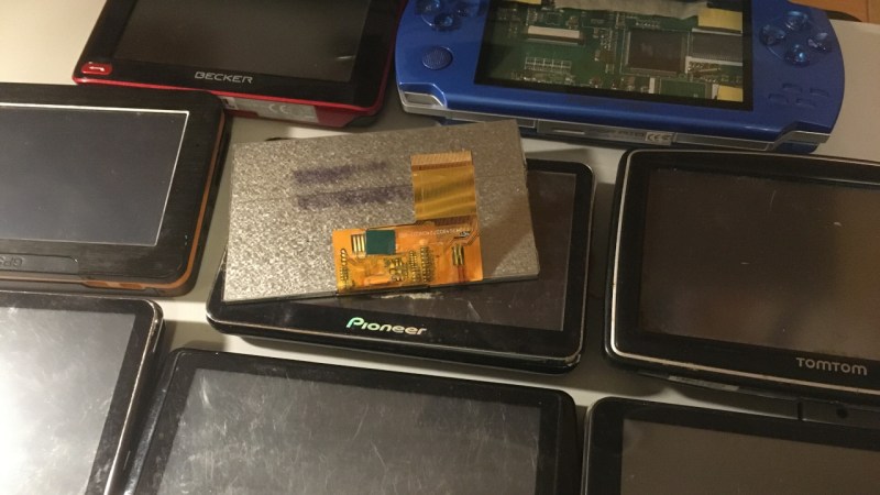
You might have seen old display panels, from 3″ to 10″, with 40-pin FFC connectors where every pin seems to be used for some data signal. We call these displays parallel RGB, or TTL RGB, or DPI, and you can find them in higher-power MCU, Raspberry Pi, and other Linux SBC projects. You deserve to know what to do with those – let’s take a look.
The idea is simple – this interface requires you to constantly send a stream of pixels to the display, and you need to send those pixels through a parallel bus. You can send up to 8 bits per color channel per pixel, which makes for 24 bits, and the 24-bit mode is indeed the standard, but in practice, many parallel RGB implementations don’t bother with more than 5-6 bits of color – two common kinds of parallel RGB links are RGB565 and RGB666. The parallel RGB interface is a very straightforward approach to sending pixels to your display, and in many cases, you can also convert parallel RGB to LVDS or VGA interfaces relatively easily!
If you’re new to it, the easiest way you can drive a parallel RGB display is from a Raspberry Pi, where the parallel RGB interface is known as DPI. This is how 800 x 480 display Pi HATs like the Pimoroni HyperPixel work – they use up almost all of the GPIOs on your Pi, but you get a reasonably high-resolution display with a low power footprint, and you don’t need any intermediate ICs either. FPGAs and some higher-grade MCUs also often have parallel RGB output capability, and surely, someone could even use the RP2040 PIO as well!
Throughout the last decade, parallel RGB has been used less and less, but you will still encounter it – maybe you’re working with an old game console like the PSP and would like to put new guts into it, maybe you’re playing with some tasty display that uses parallel RGB, or maybe you’d like to convert parallel RGB into something else while treating it with respect! Let’s go through what makes parallel RGB tick, what tools you have got to work with it, and a few tips and tricks.
Timing Makes Everything
So, you have three primary colors, and five to eight bits per color, requiring from 15 to 24 parallel lines – you push pixel bit values through these lines, one pixel at a time. There’s also a clock signal that lets the display know when it should capture the state of its parallel inputs, this signal is called a pixel clock, where each clock rising edge indicates a new pixel. The clock rate is therefore more-or-less equal to screen pixel width times pixel height times the refresh rate – say, for 1280 x 800 at 60 Hz refresh rate, you’d expect about 62 MHz. There’s also two more pins that you have to wiggle periodically – HSYNC and VSYNC, which signal a complete row and a complete screen of pixels respectively. Want to learn more? Here’s some MIT lecture materials!
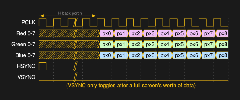
Here’s a list of common frequencies per resolution per refresh rate; on Linux, you can enter cvt 1600 768 60 into the terminal to calculate the pixel frequency for a custom resolution. You can notice that for 1280 x 800, the proposed pixel clock frequency is 83.50 MHz, which is higher than we’d expect from a simple calculation, and there’s a bunch of extra numbers in the cvt output – that’s because there’s a caveat. You’re expected to wait for a certain amount of clock pulses before and after each HSYNC and VSYNC, so, before and after each row, and before and after each screenful of data. Also, while either VSYNC or HSYNC are asserted, you’re supposed to wait for a certain amount of clock pulses too – of course, the clock is expected to keep wiggling at all times!
The specific inactivity periods before and after the sync pulse are called back and front porch respectively. So, each display has six data-less periods with certain durations – for both vertical and horizontal sync signals, there’s back porch, the sync pulse itself, and front porch. Most of the time, you can get away with the most standard durations used for most monitors, or get the numbers from a calculator like cvt if your resolution or refresh rate are a bit non-standard. If you’re working with a monitor that has an I2C EEPROM which stores EDID, you can also get this data from EDID. Would you like to learn more about those periods? Here’s a wonderful blog page, and there’s many more too!
Some displays want very particular periods, like this display that Sipeed sells, where they give you the datasheet so that you can get the exact parameters that the display is comfortable with – the back porch durations they recommend are an exact number, and I don’t know if the display would support a different one in reality, so it’s always good to know the recommended one for sure. If you’re reverse-engineering an existing display and you got the device able to drive it, this is the sort of thing that you can figure out in-system with an oscilloscope. Apart from this data, you’ll want the pinout – and, sadly, we don’t always have the luxury of checking the datasheet on this one.
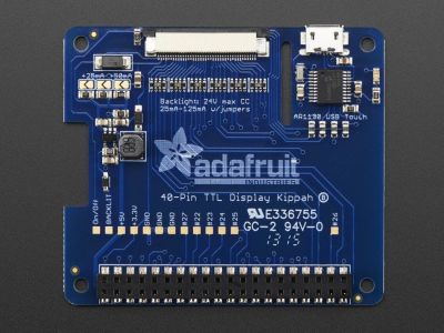
Of course, there’s standardized pinouts for parallel RGB displays! I don’t have a summary handy for you, but someone could certainly compile a table with a few pinouts and say “these are the pinouts you’re 99% likely to encounter”. Nevertheless, you’ll find quite a few pinouts that match from display to display, here’s one you’re likely to encounter on 40-pin FPC displays, and I encourage you to check places like Adafruit and Aliexpress to see which pinouts they have displays and breakouts for. Adafruit in particular has developed a large amount of parallel RGB display tech, so studying their offerings will help you a lot when it comes to parallel RGB display intricacies. If you’re reverse-engineering a display out of a known-working system, you can always try to have it display an image, then use a bench oscilloscope to find pixel clock/VSYNC/HSYNC signals, and mess with the individual pins to see which pins correspond for MSB and LSB of which color.
A Raspberry-Scented Testbench
You got the timing parameters, you got the pinout – let’s talk practice. There’s a whole bunch of things you can attach a parallel RGB LCD to – MCUs with parallel RGB interfaces, FPGAs, and quite a few SBCs. I’d say that the simplest way for an average newcomer to drive parallel RGB displays, is a just Raspberry Pi board with a 40-pin GPIO header! I do mean a Linux-running Raspberry Pi, and I don’t mean a Pi Pico running Linux through RISC-V emulation – though, without a shred of a doubt, some of yall could make that work too.

On a Pi, a parallel RGB display can be connected through the DPI interface, which will take up a whole bunch of GPIOs, but you can decrease the GPIO amount by running the LCD in 565 (16-bit) or 666 (18-bit) mode and freeing a fair few; this will limit your color range, but you might value the extra GPIOs more. Lower-bit modes are not a bad idea either – an overwhelming majority of old laptop displays have historically been driven in 565 mode and it hasn’t been much of a problem, at least, considering that those displays weren’t of stellar quality either. When wiring up the display for modes less than 24-bit, you’ll want to ground the pins for the least significant bits you’re not using, for instance, ground D0-D1 in 666 mode.
Now, the software! On the Pi, the parallel RGB aka DPI interface has a fair bit of documentation and success stories, unlike the DSI interface, which is proprietary and uses that one FFC connector near the SD card slot. It might be easy to confuse them, so here’s an easy mnemonic – DPI is Pretty hacker-friendly, and DSI is, Sadly, defined by the MIPI Alliance.
If you know the display parameters, it might be enough to put them into config.txt and go – there’s enough documentation on the parameters required, so, even if the low-level workings of the DPI peripheral aren’t exposed, you’ll do wonders with the output of cvt alone if you stick to one of the required pinouts. One weird little thing is the aspect ratio parameter. If you’re facing a display with a wacky resolution and aspect ratio, like the 1600×768 Sony Vaio display I’m about to poke at, that might be a headscratcher. However, it doesn’t appear to be a big issue – here’s someone making a 720×720 display work, and they just used an aspect ratio parameter that was close enough.
After you’ve put your parameters in, your display should Just Work. If it doesn’t and your parameters are close enough, let’s see if there’s any other wiring requirements you might have missed.
Finishing Touches
Some displays expect you to drive their backlight LEDs yourself – while sometimes it can be as simple as just a few separate LEDs, more often it’s a string of LEDs that requires upwards of 12V at certain (low) current to drive it. There’s enough backlight driver circuits and special chips online, many of them pretty cheap, and a series resistor will do in a pinch if you have a voltage source high enough. However, some displays are very particular – for instance, I’m currently dealing with a display that has LEDs in a 4-channel 8-series configuration, which forces me to add a separate boost-capable backlight driver circuit on the adapter board. That said, Mouser has great search filtering for such drivers, and LCSC has a good amount of options if you’re willing to go through the search results, so you shouldn’t have any hassle. Other displays might have a backlight driver on the panel, and will only expect a digital PWM signal for brightness control from you.
Some displays will even come with a touch panel that has its own FFC, and some will give you touchscreen controller IC signals (typically I2C) on the same FFC that carries the data pins. Careful – if you only get raw captouch panel signals, like on this iPad CM4 rebuild project, you will need to bring your own controller! Not that it’s not doable – the subsequent worklogs of that project have some great pointers. Some displays will need high voltages for the TFT internals – other displays will only need 3.3V or 5V, producing any high voltages on their own with a booster circuit, and some will have the circuit but will expect you to wire up a capacitor or two to the FFC so that the booster circuit can work. A datasheet helps with all of these, and a website like Panelook might just help with the more obscure panels, especially if you have an email address on a custom domain name. In completely unrelated news, sharing is caring!
Most likely though, you’ll get one of the pretty standard 40-pin footprints, and chances are, you’ll be able to use an Aliexpress board with it. What if you need to design your own board? For Raspberry Pi use, it’s as simple as pulling wires from the GPIO header onto the FFC header, handling the backlight and any other requirements, and options if you’re so inclined. Theoretically, you would want to length-match the parallel signals, which is to say, get all the RGB & clock & sync tracks to be the same length using wiggles, but the answers on this Stackoverflow page unequivocally that you don’t really need to do that. It’s not like it will hurt, but don’t feel guilty for omitting length matching at these frequencies, either. A better idea is having series resistors at the receiving end, something from 10 to 100ohms – those should help quell reflections that are bound to happen at DPI switching speeds.
If, however, dealing with 20-30 tracks at a time is too much for you, you’re in luck – the next article will talk about LVDS and eDP, which boil down all of the parallel RGB signals into just a few diffpairs, while achieving way better throughput! LVDS in particular is an interface where knowing the parallel RGB history pays off – as you will see, it’s basically parallel RGB in a trenchcoat.


I’ve had to adapt a couple parallel port LCD displays to microcontrollers. Most of the displays I’ve worked with have gone away from HSYNC/VSYNC entirely, and just use DE (Data Enable). DE just asserts when there is visible data out of the port. Really makes things much simpler.
For microcontroller applications, it is hard to argue for anything but 565- it fits nicely in a 16 bit word to make addressing easier, and end up using A LOT less memory. Usually, you use some form of DMA to move memory out of the framebuffer to the port, and then to the display. The DMAs I’ve dealt with deal with 16 or 32 bit words most easily (the pixel stride). You need to get the data out the port, on time, every time.
The framebuffer stores the data bit-for-bit, and will use a *LOT* of memory. 800×480 in a 565 (16bpp) depth is still 768KBytes of frame-buffer. Depending on your DMA, 24bpp may require you to use 3 or 4 bytes per pixel (4 bytes per pixel for the typical 32bit DMA which won’t do a 3 byte stride, since that could take 1 or 2 32 bit memory bus cycles plus time to re-arrange.
565 is great for embedded applications. (5 bits for Red and Blue, 6 bits for green). Few people will be able to see the difference on your typical embedded type display.
For basic GUI use even 8-bit color (RGB332) is plenty, halving the memory requirements. 4-bit palette might be useful also, but is rarely supported by DMA hardware.
I really love your display-related articles, this is solid and immediately useful knowledge.
Arya: like your articles, good content. This one was very good content. Style note–the exclamation marks are distracting! Maybe one or two per article?
Thanks!
Those little displays and their hard to solder/easy to break connectors are less of a mystery to me now!
+1
I have long wanted to match a VGA/DVI/HDMI to parallel LCD driver to a parallel-camera to H264 IP camera board – i.e. skip the parallel LCD and parallel camera, and go straight to VGA to H264 over IP. I even have the parts (driver and camera), and just need to match up the HSYNC/VSYNC and data pins, I hope! Just need to actually sit down and do it now, I’ve had the parts for about 6 years already! ‘-)
Interesting idea 🤔, come back and let us know how it works!