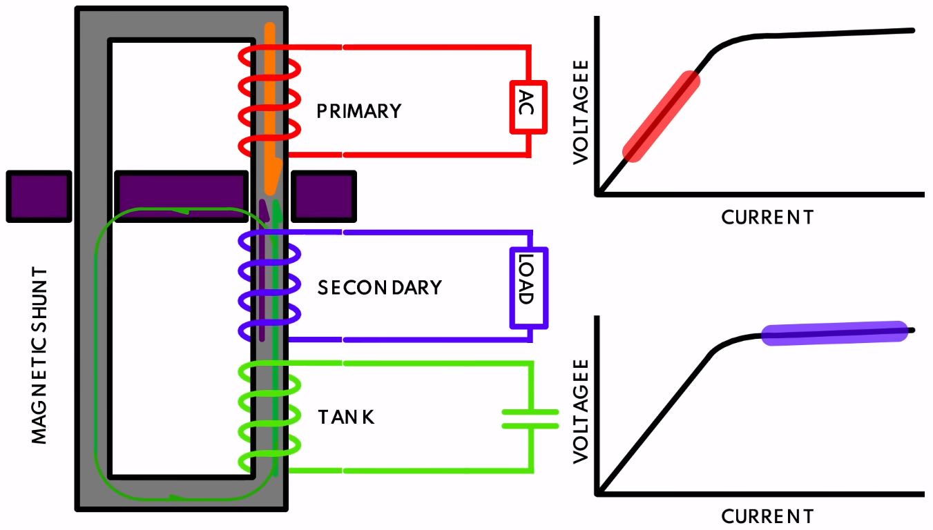
While troubleshooting the power supply of a 1970s Centurion system, [Usagi Electrics] came across a fascinating feature of these units: the ferroresonant, or constant voltage transformer (CVT). The main difference between a regular transformer and a CVT is that the former has a quite direct correlation between the input and output voltage, as the magnetic flux induced on the primary side is directly translated to the secondary (output) side.
A CVT adds a second element on the secondary side in the form of a tank circuit (LC circuit) – essentially a large capacitor – along with a magnetic shunt that ‘short circuits’ part of the magnetic flux between the primary and secondary side. The result of this is that even as the primary side is kept well below the saturation point where efficiency plummets, the secondary side is kept within this saturation region, enabling a very constant output voltage across a wide range of input voltages. For the Centurion’s power supply this input range goes from 90 to 130 VAC.
Although this is an obvious benefit of CVTs, the drawbacks are also plentiful. One is that keeping the secondary side in saturation produces more waste heat, another is that CVTs produce a distinct whine and the CVT is much more sensitive to grid frequency changes than a regular transformer. Even so, they still find many uses today where galvanic isolation and resilience against voltage fluctuations are important.
As for the reason why this Centurion’s power supply was torn down in the first place, this was due to a missing +24VDC rail, which was traced down to a dead electrolytic filter capacitor after days of crowd-sourced reverse-engineering and creating the first complete Centurion power supply schematic in probably many decades.


This stuff isn’t that rare as an element of transformers you might take apart, but it gets little attention since it’s not made of silicon. Another neat thing about them is that they can provide a constant current into a short circuit. It’s nice to have current-limiting in a transformer –> rectifier –> filter DC power supply. I guess with this kind of thing and variacs, you could even vary the limiting current seen at the actual load. It’d be fun to have a 1kW+ CC/CV power supply that was almost entirely magnetic.
Plus I guess it helps that they also clean the power up some, although they introduce their own issues especially if you have a PFC power supply running on one.
These were very common back in ’60s and sold as power stabilizers for TV sets. When I was a boy nearly all household had one.
These are still found in quite a few older electrical controls cabinets. They generated a lot of heat, but were believed to increase machine uptime. Indeed, the quality and detail was quite high of systems that had these
Henry Radio used this supply technik im in several 2K high power shortwave amplifiers, DJ7SW-Lup
I recall from fooling around with neon sign transformers (a long time ago in a high school far, far away) that most of them had the mysterious ability to limit current, usually to something like 23mA. That seems like a great idea to me now, but back then it kind of put a limit on the high voltage hijinx. Anyway, that turns out to be done via magnetic shunt, so that when secondary current gets too large, flux gets diverted away from the secondary winding. Pretty neat.
This current limit is required, otherwise the neon tubes would quickly burn out. When lit they are almost like a short circuit with a voltage drop of a few tens of volts per meter.
IBM 3278 displays used to use ferroresonant power supplies. I know this, since I started at IBM Hursley straight out of university, working on what would become the IBM 3279 colour display. Our test rigs to begin with were modified 3278 displays, with the big ferro power supplies and a huge 8vDC working capacitor. I think they were 240,000uF. (Later I snaffled one for a homebrew S-100 system).
Brings a whole lot of memories. My first real, properly stabilized power supply (ca. 1991) employed the venerable 723 and a 2N3055 (what a surprise). To this day, the frequency compensation part was the least understood section of the schematic. It is pretty impressive how you figured all that out.
Sola?
I have a few Solatrons made for vacuum tubes equipment. The new Sola supplies have switched secondary with relays to do the steps.
The one time I ran into a problem with one of these was during the development of the Data General MV20000 Super Mini. I got called in rather late in the product release cycle to help the power systems group figure out a way to minimize the growling noise made by the power supply enclosure. The dual ECL processors were pretty power hungry and they’d used a ferroresonant transformer to provide a bulk 40volt 400A supply that was then shipped out to the secondary regulators in the CPU/IO racks on a custom made pair of UL rated 000 guage wires.
A regular non-resonant conventional transformer constrains ~99% of the magnetic flux within the core throughout the cycle. The thing to remember about ferroresonant transformers is that twice per cycle the core is deliberately allowed to go into flux saturation and this creates a very large transient magnetic flux in the surrounding air space.
The power supply box was a steel enclosure and the stray flux was deflecting the enclosure beneath the transformer by a good 1/10mm at 120Hz. It sounded like you were being buzzed by a Dornier Do 17. Being days from product first ship a Q&D fix was needed. I roughly plotted the flux density beneath the transformer and interposed a quarter inch thick aluminium plate between the transformer and the steel floor. The eddy currents induced in the plate cancelled the flux seen by the steel enclosure floor – a useful application of Lenz’s Law. Worked like a charm.
The world needs more growling computer supplies.
Thanks for this tip! I will now try to un-growl my 13,8V 20A linear power supplies for ham transceivers with aluminium plates.
In the 80’s, I worked for Electronic Measurements, a power supply manufacturer. We made ferroresonant power supplies. I rarely worked with them but recall they were pretty close to spec after manufacture but were fine tuned with shims.
Some older TV sets used ferroresonent transformers in their power supply. Vague memory from the ’70s sayd that maybe these were Zenith System 3 sets. “The parts go in before the name goes on.”
These were ubiquitous in ’60s: https://curiosando708090.altervista.org/wp-content/uploads/2015/01/stabilizzatore_anni_50.jpg
There was a CVT inside each one.
The graph doesn’t make any sense. If you don’t draw current there is no voltage? He should label/number the currents and voltages in the circuit and put those on the axis of the graph
I remember seeing a distorted waveform on the output in a lab. A “bent coathanger” shape.
wasn’t it a mandatory rule to begin with changing all electrolytic capacitors in old equipments in trouble?
CVTs are used in photographic darkrooms for enlargers to maintain their lamp’s brightness for consistent exposures.
Does anyone know how to size the capacitor for these? I have an old 1.5KW constant voltage transformer and I’d like to replace the capacitor on it. Unfortunately there are no markings on the capacitor.
@John, I’m not an expert but assuming a resonant circuit at 60Hz, C=(7.04*10^-6)/L.
Just ran into this while repairing a 36V 30A golf cart charger.