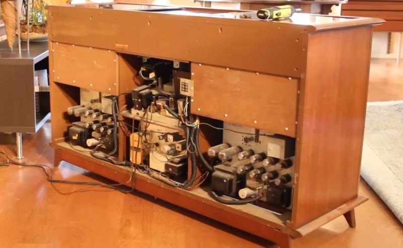
Back in presumably the early 1960s, [David]’s grandfather bought a console stereo featuring a record player, AM/FM radio and a rather astounding stereo speaker system that would be more than enough to cover a small concert hall. Having inherited this piece of auditory art after his grandfather’s passing, [David] has given the console stereo a prominent place in his living room, which is where we start the tour in a new video on the [Usagi Electric] YouTube channel.
Being a 1950s-vintage design that got produced into the 1960s in a variety of models, the Magnavox Concert Grand is an all-tube affair, with the only presence of semiconductors being the three transistors found in the ‘Phantom’ remote control. [David] unfortunately does not posses this remote control, although the receiver module is present in the unit. It appears to be similar to the 1960 1ST800F in possession by [electra225] over at the Classic HiFi Care forum, which can provide 50 Watt per channel, yet as noted in the forum post, the 44 tubes alone draw about 250 Watt, with [electra225] recording 377 Watt total with everything cranked up. Clearly a high power bill was a price one had to pay for having high-end audio back in that era.
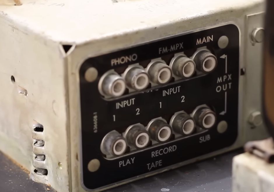
After [David] takes his unit apart – made very easy due to the modular construction – he goes through the basic circuitry of the power supply, the amplifiers and even has a peek at the circuitry of the remote control which appears to use basic frequency modulation to transfer the intended action to the receiver. All of this is made quite easy as full schematics are available for the entire system, as was standard back in those days. Interesting is also the I/O module, which features an MPX section, for demodulating stereo FM which wasn’t standardized yet at the time. Finally, tape drive connectors are available, which would have been likely a reel-to-reel unit for maximum HiFi enjoyment.
With the only broken thing in [David]’s unit being the snapped wire on the tuner of the radio module (ironically caused by the disassembly), all that was changed before reassembly was a good clean, after which the console stereo was put back and tested. Reflecting an era when HiFi equipment was supposed to blend in with other furniture, it will likely continue to do service for [David] as the world’s fanciest TV soundbar for the foreseeable future.


He’s lucky it didn’t catch fire, every single electrolytic should be checked and probably replaced, resistors should be checked too. Voltage should be fed through a variac and increased slowly while monitoring consumption.
6V6 is not a pentode. 5Y3 and 5U4 are not a dual diodes but a full wave rectifiers (there’s only one cathode). The lower half of 12AX7 is a paraphase inverter.
Nice piece of equipment however!
Wow, what a beautiful piece of equipment!
Ramping up the voltage is a good idea if the unit has sat unused for a long time. But I must say, lots of my old tube gear is still working fine with the original electrolytics. I just use it often enough that the capacitors stay “formed”. They also tend to be better quality equipment, where the capacitor’s rated voltage is well above the actual working voltage in the circuit (like 450v caps in a 300v supply).
But according to my 1968 RCA tube manual, the 6V6 *is* a pentode (it has 3 grids), and the 5Y3 and 5U4 *are* dual diodes (with a common cathode).
“like 450v caps in a 300v supply”
Of course the rating voltage should be careful chosen not by merely matching operating B+ but also with load detached (e.g. direct heated rectifier start conducting after 3-4 seconds while the load is still not warm enough).
6V6 is still a beam tetrode ad differs from pentode from not having an external connected suppressor grid (it was designed right to not infringe the pentode patent from Philips/Mullard).
On 5Y3, 5U4 probably your definition fits well but I’ve never heard them called other than full wave rectifier.
A Beam Tetrode differs from a pentode in semantics! A Pentode uses a spiral third grid (“g3” in Eurospeak, “Suppressor Grid” in Yankspeak) connected to the Cathode to suppress secondary emissions (which I don’t want to get into here, suffice to say that it’s not a desirable phenomenon…). Penta meaning 5, for the 5 elements in it:
Anode, g3 (“Suppressor” in Yankspeak), g2 (“Screen Grid” in Yankspeak), g1 (“Control Grid”), & Cathode.
Tetra means 4…but a Beam Tetrode actually has 6 elements in it! Confused? You should be. Maybe RCA was too, when they concocted the thing to supposedly “circumvent the Philips Pentode Patent”.
Funny thing then, that RCA only used their Beam Tetrode as output stage devices, & never tried to use them to substitute for Pentodes in small-signal applications…🤔
The SIX elements in the Beam Tetrode are:
Anode, 2 “Sheet-forming” Plates, Screen Grid (g2 in Eurospeak), Control Grid (g1), & Cathode…
The 2 Sheet-forming Plates were each connected internally to the Cathode, exactly as the single Suppressor Grid would be in a Power Pentode Valve.
Indeed, whether true or not, RCA claimed that the electron Beam-forming action of those 2 electron Sheet-forming Plates created in effect a “virtual Suppressor” that was actually superior to the g3/Suppressor Grid in a true Pentode…
Suppressor Grids were permanently (internally) connected in Mullard’s EL84 (JEDEC “6BQ5”).
When you speak of “externally connected”, I assume that you actually mean that there was a dedicated pin on the base of the Valve for connection to the g3.
But no Engineer worth their salt ever did anything other than connect that g3 pin to the Cathode!
They were separated in Mullard’s equally famous EL34 (yet its JEDEC exact functional equivalent, the 6CA7, is a Beam Tetrode).
Although in the superior version of the EL84 made for Television Audio Output Stage service, JEDEC type 6GK6, there IS a separate g3 pin📌!
Confused? You should be! 🤪
The only purpose I ever found that justified connecting the g3/Suppressor to anything other than straight to the Cathode was when Power Pentodes were used as Line Amplifiers (“Horizontal Deflection Amplifiers” in Yankspeak) in Television Receiver service.
There, you might see a rather low voltage, usually no more than 28VDC above Cathode potential, applied to the g3/Suppressor Grid so that it would help to suppress what the Yanks called “Snivets” (“Barkhausen Oscillations” in Eurospeak), or what I simply call either “Parasitic Oscillations” or just “Parasitics” for short.
And yes, valves are more linear than transistors. On average, THD in a single-triode cascade-type gain stage, before any NFB is applied externally, is usually about ⅒th of what it is in its transistor equivalent!🥳
And unless your ears are firmly lodged up your behind, this is plainly audible through source & playback equipment of the lowest possible distortion. Which are NOT any contemporary 16-bit Digital sources with their 0.5% THD @ -40db below 0VU!😬
Even a cheap 1975 cassette deck can beat this by an order of magnitude!😏🤧
He said in the video, that he’s been using it actively for years. So, no need to slowly bring up something that’s already known functional.
Those tubes are gold I’m an old radio head ( cb) I built several radio’s. Radios that could talk all over the world. Now they have digital amplifier’s . But the best sounding radios use tube amplifier’s. You see you want to have some swing in that thing to sound loud and proud. A digital amplifier when keyed send the power to the radio. A tube amp is another animal. If your radio has a variable what you do is put about 1/2 a watt into the amp. That way you hear nothing until you modulate. If done properly you can make 500 watts sound like 5000. There’s truly an art to making it sound correct.i used to run an add to but old tube tv sets just for the tubes. Now you can only unmatched Russian tubes. The best are the old RCA’s which go for a coye hundred dollars a piece that was 20 years ago so……
“Clearly a high power bill was a price one had to pay for having high-end audio back in that era”
But on the flip side, it would reduce the costs of heating your living room.
well, the important thing with these all tube circuits is not only do they Not add stressful or fatiguing elements to recorded material but they have the ability to FILTER OUT a lot of annoying/stressful or fatiguing
aspects of badly recorded music especially early crude digital recordings.
Please explain your claims mathematically.
I doubt that such an explanation exists, given that even early Denon 13 bit PCM recordings still sound gorgeously…
Are you looking for an explanation of how a filter works, an analysis of the difference between the soft round-off of an overdriven tube versus the harsh clipping of an overdriven basic transistor, or just an argument?
I’m from the future, where we just use solid state circuits at a medium volume and all our music has been edited and compressed so much that we can’t hear the difference. But if you’re going to have harsh sounds, squared-off signals are unpleasant.
Sorry I was talking about fidelity and I was wrong.
At clipping surely tubes are a lot better to hear. My daily driver is a 3W SE amp.
Just an argument. A claim that the tube amps “filter out” part of the sound doesn’t seem like a good thing to me. On the other hand, your reference to soft clipping makes sense (but that’s not filtering).
Well, everything is a filter, even if it’s not made to be one, because everything is an inductor and/or capacitor, but I think you mean that the effects on the sound aren’t exactly low, high, or band-pass, which is true. There is some of that filtering; one part is for instance in the audio transformers that adapt the output to a more usable range. They don’t pass DC or high frequencies. Other parts have similar effects.
But also, if your black box takes in a square-ish input wave and returns a softly curved one, it has filtered out the higher-frequency components which make up a square wave when represented as sines. So while that characteristic is what you see when overdriving them, during the time it’s happening it’s a kind of filtering in at least my interpretation. And transients can be a cause of such a thing, rather than continuous overdriving, so maybe that’s what the original person was thinking of?
The only reason I believe SOME pople like tube amplifiers is that they are typically quite asymmetrical vs. transistor circuits tend to be symmetrical. Thus tube amplifiers produce significant distortion in the form of 2nd harmonics (which may sound pleasant) whereas semiconductor amplifiers only produce odd harmonics (which probably are unpleasant). That is my guess. Everything else, I don’t make any sense of it.
Tubes are inherently linear, transistors are not.
Transistors heterodyne, these unwanted frequencies must be filtered out.
It is that simple, of course the details of the designs are not. Class A forever! Heat your house by turning the volume down.
Tubes are linear? In what planet? The main “linearizing” component is the negative feedback loop, present in both transistor and tube systems. If you see the amplifier schematic in the video the “lower input tube” gets its input from the output, yes similar to the + and – inputs of an opamp. Negative feedback for you.
@Capo – There’s people who use tubes without feedback, because they can be linear enough to get away with it.
Yes tubes,some of us musicians prefer EL&34s & Groove tubes and such ,over plug-ins ,interfaces, enhancers,etc & other phony nonsense & fake music used today
High THD + human ears = good fuzzy feelings
So… all that talking and we don’t get to hear what it sounds like ? (Or did I miss that part). Major let down…
And how would you propose to do that? Listening to a pair of speakers through another pair of speakers (and a microphone and YouTube’s compression…) doesn’t seem like any way to actually evaluate anything.
Just noticed that the guy in the video cannot distinguish between the mains and the output transformer xD
The input switching undoubtedly leaves in the option of AM and FM in the 2 channels, one each left and right.
Ft. Wayne’s finest. The one time rival to Detroit.
Ahhh… Yes, I remember playing with tubes. It’s hard to forget when you get across the 450V B+ voltage. Yup, I remember it well. I had to change my pants right after.
Builds character
Tubeway days now seem so unreal we are glass i dream of wires
Tubes are just wonderful devices that indeed color the signal audio output in a good way.
Speaking of filtering, I believe it is indeed a necessary part of the signal chain and is why audio line stages include tone controls. Hi-Fi audio output rarely is 100% linear or flat output of the original recording.
Rarely does a master recording end up mixed flat and without signal enhancement.
Some folks will always argue the attributes of 100% analog vs digital audio. Each of which has its own merits and faults. For instance a vinyl recording is limited in its ability to reproduce near the same dynamic gamut of an MP3 however, not all of the dynamic range is useful or supposedly perceived biologically by the auditory sensate . Both are not reproduced the same way. As the MP3 compromises resolution the vinyl compromise extended spectrum or width. Both mixdown with different tonal reproduction curves.
Ever listen to an album direct analog from the stylus without RIAA filtering that is usually built into the phono Preamp stage?
Much of the differences between tube and transistor technologies is in the practical application and topologies of how the devices are applied.
There are transitor topologies that are designed as voltage amplifying devices that utilize audio transformers similar to tubes, just as there are tube topologies that have been designed as current amplifying that output direct to unconventional transducer devices . Maybe it is more so a difference in conventional and accepted legacy design topologies. The common accepted designed applications are more so attributable than the actual limitations of the component device utilized.
I suspect that it what creates the big wide rift between hollow state vs solid state.
I think also that we have just begun to quantify many of the contributing properties that make for a pleasant vs not so pleasant perceived listening experience. Some of which nuances are indeed attributable for good sonic composite and others no so much… It’s gold or it’s chaff and some bit of both and a market rich for snakeoil everywhere in between.
Wow, very nice. When I was a kid we had a Curtiss-Mathis console like this, but way bigger and with a 25 inch b&w TV. I sure wish I still had it, but the folks got rid of it in the 70’s.
On the input section of the Concert Grand stereo, which was the left channel: 1 or 2?
I have the remote control for this stereo.
https://i.postimg.cc/65Wkv93Y/23-Magnavox-Remote-c.jpg