FDM 3D printing traditionally operates on a layer-by-layer basis, using a flat bed to construct parts. However, [Humphrey Wittingtonsworth IV] demonstrates in his video how this process can be significantly enhanced in terms of mechanical strength and print speed by experimenting with printing on a rotating rod instead of the standard flat bed.
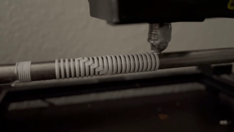
[Humphrey] modified a Creality CR-10 3D printer by removing the bed and installing a regular 8mm linear rod under the hotend. The rod is rotated by a stepper motor with a 3:1 belt drive. This lets him use the rod as the printing surface, laying down layers axially along the length of an object. This means parts that can stand up to bending forces much better than their upright-printed counterparts.
Additionally, this rotational action allows for printing functional coil and wave springs – even multi-layer ones – something that’s not exactly feasible with your run-of-the-mill printer. It can also create super smooth and precise threads as the print head follows their path. As an added bonus – it could also speed up your printing process as you’re just spinning a slim rod instead of slinging around an entire bed. So cylindrical parts like tubes and discs could be printed almost as quickly as your hotend can melt filament.
Of course, this approach isn’t without its challenges. It works best for cylindrical components and there’s a limit to how small you can go with inner diameters based on your chosen rod size. Then there’s also the task of freeing your prints from their rod once they’re finished. [Humphrey] addressed this by creating mesh sleeves that snugly fit over his center rod. This limits how much melted plastic can adhere to it, making removal a breeze.
This is not the first time we’ve seen experiments that deviate from flat layers. It’s possible to print overhangs without support using non-planar slicing, and adding a fourth axis for the hotend.
Thanks for the tip [George Graves]!


Awsome, basically laser cladding but with a 3d printer and plastics, nicely done!
Neat implementation & great enthusiasm, unfortunately not the first. Many prior examples including: https://www.youtube.com/watch?v=kv-r4HBG7lQ
Yeah, only you care that it’s not the first. What a petty comment.
The title of the linked YouTube video literally starts with “i made a new type of 3d printer”, which is what Eph was surely responding to. Printing on a rod is awesome, and something I’ve wanted to do forever, but it’s not ‘new’ by any stretch (which is okay).
Ironic that you’d call *their* comment petty.
3D printing on a rod is known at least since the 16th century:
https://en.wikipedia.org/wiki/Baumkuchen
Cooool, I wanna see a scale working model of a Sequential gearbox shifter now, since it works off a channeled shaft like the one pictured.
This is really cool – like the inverse of a lathe!
Additive latheying?! Instead of additive manufacturing.
WE still Stuck in additive manufacturing with means small amounts of pieces. Are Out there example for additive industriallisation in other words mass Produktion in a Taylorisation way?
Yes there are companies out there that have large print farms that make mass production 3D printing feasible. One example is Slant 3D who also have a YouTube channel.
LOL at Slant 3D – so many other companies that have print farms.
Additive turning
Yes, it should absolutely be named the Antilathe
I wonder if larger prints would have to take the increasing mass into account as the print progresses.
Depends on your chosen acceleration. regular Cartesian bed slingers also have to haul around the printed mass, but it’s usually not a problem. in this case it looks like moment of inertia can go very high easily though, so maybe you can reduce acceleration via gcod every other X layers
One such way may be to define it as linear acceleration not angular acceleration, the further you get from the centre the smaller the angular acceleration or velocity will be for a given linear acceleration or velocity. So constant linear acceleration would mean very quick acceleration near the centre and slower acceleration the further out you get.
He describes the limiting factor as how fast you can melt the plastic. But sure if you extend this idea out you will eventually need to consider momentum as a squared relation ship of radius.
What a clickbait title, came here looking for 3d printing on fishing rods, so disappointed…
Who says you can’t do that with this idea?
I initially skipped over this article because I had no interest in fishing accessories. Which makes it anti-clickbait.
Soon.
3d printed condoms.
I can’t wait!! So like, would it be a Print In Place Design?! If not, we need to know the MINIMUM internal diameter. They don’t call me Dongus Minimus for nothing
Not enough resolution for me 😭
Hopefully not printed in place.
Interesting. I wonder if, using a sensor to measure and thereby adjust for the imperfectly round and/or intentionally varying diameter profile along the axis, one could print directly on bottles.
I suspect this may already be possible using existing mesh bed levelling functions, ‘just’ swap your Y axis to rotational and enable a high count of probe points on a touch or load cell z probe. It would be fun to play with this.
This is actually a pretty good idea and reminds me of the laser engravers that can cut on any surface or round objects.
In reality all of the hardware is already there and so is most of the software. We have many kinds of bed probes but the printer expects a flat bed, it may be wouldn’t take too much, especially with arm mounted extruders and hot ends to probe an existing object, create a rough 3D model and then slice a model to be printed on the object.
You could combine this method with continuous filament embedding like the markforged x7 and make 3D printed COPVs.
A dedicated version of this could be much simpler/smaller than a full 3D printer, and thus cheaper I would think.
Additional remark: That desktop angle on the video is not working for me, I could not watch that for long.
4 axis milling is very similar, code 2ise anyway. I’m sure there are many four axis mailing solutions. That would work great for this four axis adding. Fusion 360…
So apparently this is possible (or was teased to be possible) on a Snapmaker Rotary Module; https://youtube.com/watch?v=ImvLxCmO-_8&si=GZlP-jVZJS-4VTD7
(Time stamp 2:23, can’t do it from the mobile app for some dumb reason)
The big barrier for this type of printing is the software, but if it already exists for Snapmaker I wonder if it can be jury rigged to work for a modified or diy printer? Or if anyone has spent the thousands of dollars on the Snapmaker let me know if you’ve got experience with rotary printing lol
You could program a y axis that is “flat ” in software but (OD) long that either restarts when it reaches y max or rewinds to 0 like a bedslinger (for straight rods) and use a bl touch only on 1 straight length of the bottle to create a revolving profile like in autodesk. (For bottle shapes) . If you’re familiar with 3d printing orientation then you’d already know that rotational axis printing could make some KILLER strong springs, gaskets, lattuce meshes because of the continuous strands for additional strength
Is there a modification tutorial?