Submitting a new device for electromagnetic compatibility (EMC) testing seems a little like showing up for the final exam after skipping all the lectures. You might get lucky and pass, but it really would have been smarter to take a few of the quizzes to see how things were going during the semester. Similarly, it would be nice to know you’re not making any boneheaded mistakes early in the design process, which is what this DIY TEM cell is all about.
We really like [Petteri Aimonen]’s explanation of what a TEM cell, or transverse electromagnetic cell, is: he describes it as “an expanded coaxial cable that is wide enough to put your device inside of.” It basically a cage made of conductive material that encloses a space for the device under test, along with a stripline going down its center. The outer cage is attached to the outer braid of a coaxial cable, while the stripline is connected to the center conductor. Any electric or magnetic field generated by the device inside the cage goes down the coax into your test instrument, typically a spectrum analyzer.
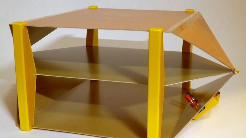
[Petteri]’s homebrew TEM is made from a common enough material: copper-clad FR4. You could use double-sided material, or even sheet copper if you’re rich, but PCB stock is easy to work with and gets the job done. His design is detailed in a second post, which goes through the process of designing the size and shapes of all the parts as well as CNC milling the sheets of material. [Petteri] tried to make the joints by milling part-way through the substrate and bending the sheet into shape, but sadly, the copper didn’t want to cooperate with his PCB origami. Luckily, copper foil tape and a little solder heal all wounds. He also incorporated a line impedance stabilization network (LISN) into the build to provide a consistent 50-ohm characteristic impedance.
How does it work? Pretty well, it seems; when connected to a TinySA spectrum analyzer, [Petteri] was able to find high-frequency conductive noise coming from the flyback section of a switch-mode power supply. All it took was a ferrite bead and cap to fix it early in the prototyping phase of the project. Sounds like a win to us.


I’ve been through this a few times and helped our hardware engineers (mainly by driving engineering versions of software, but also, with some radio knowledge).
What would be interesting is whether the TEM cell readings could be quasi-calibrated by taking the same DUT to an accredited lab and getting their results.
Then you could draw limit lines for your TEM cell which would ensure even better chance of success with the real thing.
Bingo … FCC Emissions testing is expensive especially if your device fails and requires significant rework and retesting.
FCC + CE in a certified lab in Shenzhen, $740.
And on the next day your device can be found on Shenzen market for $30.
As an ex EMC engineer I can say from experience that while TEM cells can measure radiated emissions they are very difficult to calibrate and results are not repeatable and would never be considered as an appropriate measurement technique by an accredited body they can be used to resolve problems by performing relative measurements – before modification and after modification.
The TEM cell looks to be well designed and implemented and the integrated Line impedance stabilization network is a nice touch.
Wow, he created a parametric FreeCAD design for the TEM cell. Amazeballs! I might just build one up and order some of those Tekbox LISNs, for the effort he spent building his own vs the performance, I think I can convince the boss-man that a couple of small LISNs are cost effective.
Parametric FreeCAD? Wait, what?
Calibration may be difficult compared to some other methods, but if you compare it with a handheld near field probe this is going to be much more easier and more betterer.
But instead of complaining, I am more interested on how to get some kind of reliable calibration. What would such a device look like?
I’m thinking of a PCB with an coil printed in copper combined with some test signal generator. Designing the inductor as a PCB makes it size fixed for anyone using it. Once someone with a calibrated test setup has done some measurements, you can have some confidence to get comparable results within a fee dB. Is a standard function generator (of let’s say 10MHz) enough for calibration purposes, or do you also need hundredths of MHz test signal for calibration? You likely also want to adjust the amplitude to have a defined test current though the inductor instead of the voltage output of a regular function generator, because of resistance differences of variations in etching width.
If higher frequencies are needed for calibration, then maybe integrating an oscillator circuit on the PCB is a better option.
I also was curious about the size of this thing, and after a bit searching, he has a drawing on his website. The outer plates are 300x350mm and the distance between the outer plates is 200mm. For DIY it would be nice if this thing can be folded flat for storage. Putting in (piano?) hinges would probably degrade it’s performance. Maybe those foam strips with a metal mesh around them can be combined with hinges to get a good connection.
I’ve been considering buying Tekbox TBCG1 to try to get some kind of calibration for the TEM cell. But the sensitivity depends on DUT size also, so it will always be just in the right ballpark.
Yeah, a folding or somehow assembled-on-need design would be nice for storage. Copper braid soldered across hinges would probably be plenty good. Though even piano hinges by themselves could work.
“an expanded coaxial cable that is wide enough to put your device inside.”
My first TEM cell was made from cardboard and aluminium foil… Worked perfectly fine :)
The problem is simply the size… You cannot use the full height and you would need to do a 12 faces measurement (6 sides X 2 polarizations)… Now with my bigger GTEM I can do this and the correlation is pretty good.
Big TEM cells are just too limited with their upper frequency.
But you can go even cheaper and simpler with just 2 plates… https://www.oe3hkl.com/hf-measurements/offener-wellenleiter.html
Again, pretty limited and even more problematic for immunitytesting outside a shielded room.
To be honest, a simple TV antenna 1m from your device gives you better results than the TEM cell. Get 2 of them (they are cheap after all), calibrate them and you get meaningful measurements.
73
Hey, using a TV antenna is actually a great idea. The directionality should at least attenuate other interfering signals a bit.
I have been considering building a biconical antenna, but there would be just too much interference here in a city environment.
Both TEM and GTEM are good mainly for debug, once you know what the spectrum of your device is and where need to be fixed, you may use them to compete with a modified devices. Calibration of TEM is pretty much impossible task with many variables and unstable results. Te GTEM theoretically can be calibrated and used for precomplience, but is not an easy task.
On other hand many standards refer also to open area test sites, so a calibrated antena will do the job if the noise floor is reasonable.
Brilliant, thanks for sharing, [Petteri Aimonen]. I might have to build one of these.