One of amateur radio’s many interests comes in portable operation, taking your radio to an out of the way place, usually a summit, and working the world using only what can be carried in. Often this means using the HF or shortwave bands, but the higher frequencies get a look-in as well. A smaller antenna is no less the challenge when it comes to designing one that can be carried though, and [Thomas Witherspoon] demonstrates this with a foldable loop antenna for the 2 metre band.
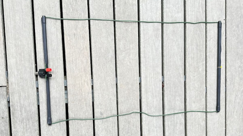
The antenna provides a reminder that the higher bands are nothing to be scared of in construction terms, it uses a BNC-to-4 mm socket adapter as its feedpoint, and makes the rectangular shape of the loop with pieces of fiberglass tube. The wire itself is flexible antenna wire, though we’re guessing almost any conductor could be used. The result is a basic but useful antenna that certainly packs down to a very small size, and we can see it would be a useful addition to any portable operator’s arsenal.
If you’re a 2 metre band user, this certainly isn’t the first time we’ve visited lightweight antennas for this band.


Yes any wire could be used, but knowing the propagation speed and thus the length gets tough
I belive the speed is mostly the same for all plain wires or the difference is negiable. There is a difference when dealing with coaxial cable with regards to the dielectric material used. Line ladder and normal wire have the same propogation speed. Wires used for antennas are mostly CU, steel or AL
The insulation can affect things, as can gross differences in the wire. But generally not so much that it’s hard to adjust. J-poles are thrown off slightly when made of ladder line inside PVC because of the PVC.
Use a VNA or an SWR meter for tuning ;)
wavelength does not deal with propagation speed.
It absolutely does.
Pretty sure that no matter what the wavelength/frequency is, it all travels at the speed of light.
It does, but the speed of light is different in different materials.
However, the difference between its speed in air and in vacuum is so slight as to be completely irrelevant to a 2m antenna. The difference for a full-wave antenna is the thickness of a mechanical pencil lead.
Thickness of a pencil lead? Wow, that’s just ten millionths of a football field!
Not in any meaningful way. The difference in the speed of light in oxy-nitrogen mix vs vacuum is so slight as to be immaterial in this application.
Specifically, it is three-hundredths of a percent different, so a full-wave loop tuned for 146.52MHz in air would be 2045.47mm long instead of 2046.09mm long for vacuum–a difference of .62mm, or approximately the thickness of a mechanical pencil lead or notebook cover, well within the typical tolerances for someone hand-cutting an antenna, and completely irrelevant for a 5kHz-wide signal.
A thing being /technically true/ does not make it /materially relevant/. ;P
What is the radiation pattern? If the dimensions were posted, then someone could model it.
I use a ladder dipole for 2 meter rally racing marshall work. Hauled up in a tree on some Paracord, the dipole has enough db gain to get out to net control from valleys and low places on the stages. Packable and coiled in a loop, can carry on a motorcycle and use with some coax to a handheld radio or mobile transceiver
While Thomas K4SWL posted this on his QRPer website, the original article makes clear that this was submitted to him by Andrew VK2ZRK.
This antenna is of the type known as an oblong loop, which is actually rectangular in shape despite its name. The two vertical sides are each twice as long as the top (length of sides in a 2:1 ratio). My understanding is that, when fed in the centre of the short side (the bottom in this case) the feedpoint impedance is 50 Ohms, which is an ideal setup for most transceivers (which expect an antenna system with that impedance).
One caveat is, as far as I know, the radiation pattern is *horizontally polarized*, which is great for single sideband voice, CW, and digital modes on the 2 m band (where horizontal polarization is standard) but is the wrong polarization for people communicating by FM voice with HTs. But I welcome correction or elaboration on this point.
I fully agree. That’s why I said that it should be modeled.
If the loop was square, then feeding it on the bottom would produce horizontally polarization, and feeding it on the side, vertical. But in this case, I’m not sure.
I can’t run EZNEC anymore because I use Linux (Debian 12 KDE). I guess I’ll have to install and learn a Linux compatible modeling program.
You could use fiberglass tent “poles” with the elastic inside which collapse and assemble in seconds. 3D print ends and corners so no metal ferules are in the loop. This will make setting up a series of snaps and have a rigid loop that can be moved and such.