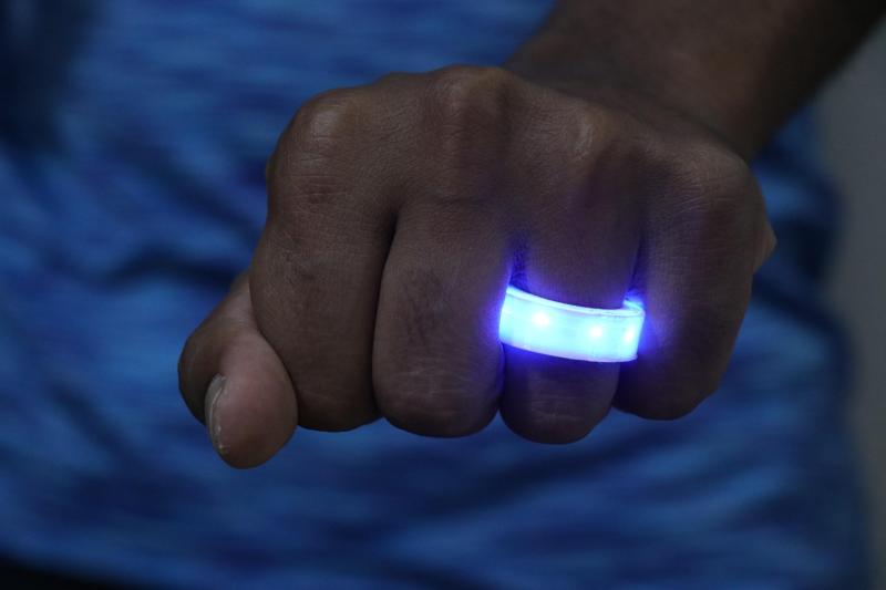
We’ve seen our share of light-up jewelry over the years, but for some reason — probably power — it’s almost always earrings or necklaces. So when we saw [ROBO HUB]’s LED ring, we had to check it out. It involves a bit of behind-the-scenes action in the form of a battery holder that you palm, but the end effect is quite cool.
Essentially, this is a 3D printed ring with SMD LEDs painstakingly soldered together in parallel along a pair of thin copper wires. The ring itself is in two parts: a base, and a cover to diffuse and protect the LEDs. A pair of wires run out from the ring and connect to a printed coin cell holder.
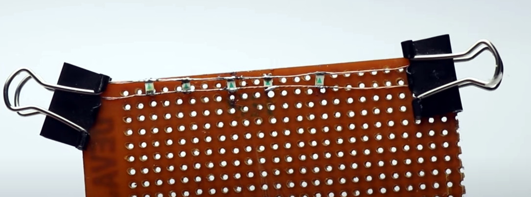
One thing we like about this build is the way that [ROBO HUB] handled the soldering of those tiny LEDs — by binder-clipping the ends of the wires to a piece of protoboard at just the right distance apart. Be sure to check out the build video after the break.
So, is there a way to do this without having to palm a coin cell? Yes, and it involves a tiny capacitor and an inductive charging bracelet.


Why wouldn’t you just put the LED on a cheap flex PCB from china, this is so bulky it looks like you’ll have dents in the adjacent fingers after a few minutes
Ever wear a flex pcb as a ring? That would probably cut into your skin you more than a traditional sturdy ring.
You neglected to notice that the ring in the picture is constructed by soldering SMD LED’s directly to copper wire…. Which would be much sharper than any flex PCB. And besides, it obviously would be potted or otherwise enclosed just like this one. Always read posts before commenting.
You want it smaller? Embed it in epoxy and use smaller leds. Flex pcb isnt that great- how would it be any slimmer soldering to flex pcb vs soldering to copper wires? The circuitry isn’t the thing making this bulky, it’s the enclosure/diffusor (which means that even with a flex pcb, the enclosure issues are still present).
What sort of LEDs are those? They look normal. But if they are then, given the lack of a series resistor or current controlled power supply, they’d burn out in moments when exposed to the full current driving ability of even a pretty tiny battery. One would only need one series resistor, run it from the lower-voltage wire loop to the the battery’s gnd terminal, and trust the LEDs to be ok when all paralleled up between the power (higher-voltage, +ive battery terminals) rail and that lower-voltage rail.
CR2032 batteries have a moderately high internal resistance, and is used a fair amount instead of adding a separate current limiting resistor. But it depends on how bright you want the LEDs to be.
I’m playing around with a dollar store string of multicoloured LEDs, and it’s surprisingly bright with only 10mA of current for the *whole* string, instead of 10mA each like I normally aim for.
It’s all about COMPLIANCE. It just so happens that the voltage-vs-current-drain curve for a coin cell limits the current to a safe range when connected to an LED, which has a very non-linear current-vs-supply-voltage curve.
I’m a little surprised that the LEDs are naturally balanced enough to get an even current distribution, though. I would’ve expected at least one or two to be noticeably brighter or dimmer than the others.
I’m still amazed how “identical” modern LEDs of the same type are.
Putting LEDs in parallel with a single series resistor definitely didn’t work in the Eighties, using the LEDs in Tandy/Radio Shack N-in-1 Electronic Projects Labs: only a single LED would lit, all others would be completely dark.
I don’t mean to dunk on this but it’s pretty ugly. Why not just a couple of leds shining into the end of a bend light-pipe? It could be thinner, and you wouldn’t see the individual leds.
add peltier power