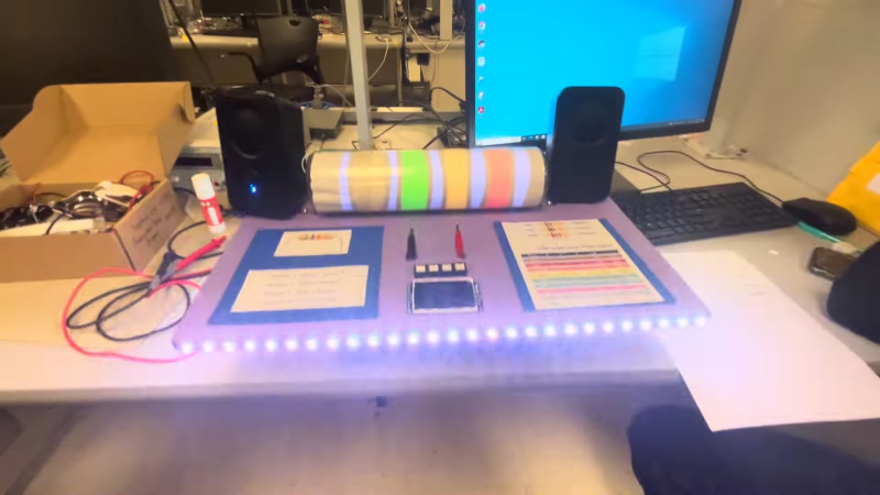
If you’ve got a resistor and you can’t read the color bands (or they’re not present), you can always just grab a multimeter and figure out its value that way. [Giacomo Yong Cuomo] and [Sophia Lin] have built an altogether different kind of ohmmeter, that can actually spit out color values for you, and even read the resistance aloud. It’s all a part of their final project for their ECE 4760 class.
The build is based around a Raspberry Pi Pico. It determines the value of a resistor by placing it in a resistor divider, with the other reference resistor having a value of 10 kΩ. The resistor under test is connected between the reference resistor and ground, while the other leg of the reference resistor is connected to 3.3 V. The node between the two resistors is connected to the Pi Pico’s analog-to-digital converter pin. This allows the Pico to determine the voltage at this point, and thus calculate the test resistor’s value based on the reference resistor’s value and the voltages involved.
A large fake resistor provides user feedback. It’s filled with addressable LEDs, which light up the appropriate color bands depending on the test resistor’s value. It’s capable of displaying both 3-band, 4-band, and 5-band color configurations. While six-band resistors do exist, the extra band is typically used for denoting temperature coefficients which can’t readily be determined by this simple test. It can also play audio files to announce the resistance value over a speaker.
It’s a neat project that surely taught the duo many useful skills for working with microcontrollers. Plus, it’s kinda fun — we love the big glowing resistor. We’ve featured some other fancy resistors before, too!


That’s interesting as a µC project but I’m not sure it’s very practical as a professional tool :
– Color coding once learnt stays inside your brain forever.
– Talking machine is no help with a noisy surounding and needs a stable measure.
– But a continuity beep is very helpfull.
– Reading a value makes it easier to memorize, more than a spoken value.
– Autoranging is great.
Just my two pence !
Agreed. I wrote an alexa skill which did this, and presented it in Cambridge makerspace a few years ago. The punchline was that by the time I’d finished coding it, I’d learnt the colours to not need the code I’d written!
There’s always one…
It seems no one mentioned that the real application of this device is for the blind technian or engineer. Their are very few talking meters available. I know of one . The color fetcher is great if your sighted. I learned the color code when I was twelve . I’m seventy-eight now and I still know it.
The first two digits 0 and 1 are hard to distinguish with RGB and external white light changing luminescence values of those dim colors. Grey gets into a very grey area.
I judge a lot of college level projects and this is interesting but could be more useful.
Questions I would have asked would include “You can measure the resistance to 1/100,00th of an ohm (I thought I saw 5 decimal places)? Is that really accurate? What’s limiting your accuracy?” or “Could you have included units in the audio output (like “4 thousand, 3 hundred, and 7 ohms)?” or “How might you be able to display a reasonable tolerance value given the measured value (one way might be have a table of standardized resistance values and compare your difference between your measurement and the closest common value)?”
This would have been a “B” sort of project at best IMO – interesting but could have been executed in a more useful way. Not a waste of time but a little more thought on the UI and presentation would go a long way.
Nefty, they could’ve multiplexed multiple resistors for the voltage divider to improve the range and distortion of the inverse relationship and resolution of the ADC. I think that’d be beyond the requirements of the project but would be a nice little step without changing things too much. Audio is an easy thing to mess up so I’m sure that’s what they spent most of their time debugging.
I love seeing these projects!
I’ve learned the color codes when I was 7 or 8 years old in the mid 80ies and can read all the E12 values on sight because the color pattern gets stuck in your brain after a while. I can just pick a 15k resistor out of a pile of random resistors in seconds for example. These color codes are sometimes used on old capacitors and inductors as well.
But for E24 and higher, 1% or more accurate and with background paint that’s not neutral it gets trickier.
I rarely use through hole resistors anymore, SMD all the way! I do consider SMD resistors are also diy friendly, especially considering you don’t have to drill holes in your home made PCB :)
I love SMD resistors but I wish more of them had their resistance written on them, instead of being just blank. Ditto SMD capacitors.
I don’t want any machine to spit stuff out at me.
Yes but does it spit out colourful language when it goes out of range?
I am colour-blind and registered blind. I can still drive in an adapted car. I use different lenses because and voice over text. I have to use a scanner reader for all the light background mail I receive.
The world is pretty ignorant.
I am very interested in this project.
Congratulations to the person or persons involved.
I am sending a virtual hug.
Thank you.
> light up the appropriate color bands depending on the test resistor’s value
This has been tried a few times in the past. Turns out “brown light” isn’t really A Thing, then “grey” and “white” light can’t be told apart unless they happen to be next to each other.