Although resistors are hardly among the most exciting components, they are arguably one of the most important ones, as anyone who has done any amount of circuit design and debugging can attest to. So too with a single carbon resistor in a vintage Metrix oscilloscope that [CuriousMarc] recently repaired. After recapping the board there was still a major issue that got traced down to said resistor. After replacing it with a fresh resistor obviously this meant doing an autopsy to see why the old resistor had failed.
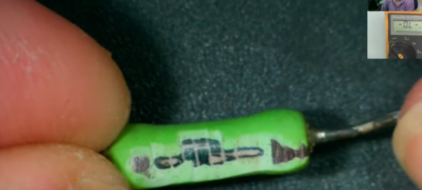
The 20 kOhm-rated resistor looked fine on the outside, with no obvious damage or discoloration, but it measured around 0.843 MOhm. To get to the insides [CuriousMarc] asked his friend [TubeTime] on how to proceed. The answer here was sandpaper and a lot of patience, and thus the experiment to see how much sanding it takes to get to the core of a fairly big resistor commenced.
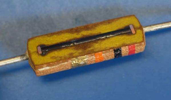
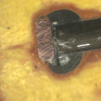
Ultimately the insides were revealed, and they turned out to be rather interesting, with what looked like a glass tube filled with what would be the carbon-laden material between the two lead terminals. From poking around a bit at these insides it would appear that the failure mode was a degraded contact between these terminals and the carbon material. Considering that this resistor is many decades old and has gone through many thermal cycles and potentially various kinetic events some fractures are probably to be expected.
Perhaps most fascinating is the construction of this carbon resistor that looks to be a step above that of the average carbon resistor that [TubeTime] has taken apart over the years.
Continue reading “Autopsy Of A Failed Vintage Carbon Resistor”