Every once in a while we get wind of a project that we’re reluctant to write up for the simple reason that it looks too good to be true. Not that projects need to be messy to be authentic, mind you, but there are some that are just so finished and professional looking that it gives us a bit of pause. [Sebastian]’s programmable precision resistor is a shining example of such a project
While [Sebastian] describes this as “a glorified decade resistance box,” and technically that’s exactly right — at its heart it’s just a bunch of precision resistors being switched into networks to achieve a specific overall resistance — there’s a lot more going on here than just that. The project write-up, which has been rolling out slowly over the last month or so, has a lot of detail on different topologies that could have been used — [Sebastian] settled on a switched series network that only requires six relays per decade while also minimizing the contribution of relay contact resistance to the network. Speaking of which, there’s a detailed discussion on that subject, plus temperature compensation, power ratings, and how the various decades are linked together.
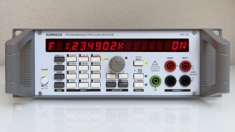
For as much that’s interesting about what’s under the hood, we’d be remiss to not spend a little time praising the exterior of this instrument. [Sebastian] appears to have spared no expense to make this look like a commercial product, from the rack-mount enclosure to the HP-esque front panel. The UI is all discrete pushbuttons and knobs with a long string of 16-segment LEDs — no fancy touch-screens here. The panel layout isn’t overly busy, and looks like it would be easy to use with some practice. We’d love to hear how the front and rear panel overlays were designed, too; maybe in a future project update.
This honestly looks like an instrument that you’d pay a princely sum to Keithley or H-P to own, at least back in the late 1990s or so. Kudos to [Sebastian] for the attention to detail here.


Would genuinely have had trouble working out that’s not a commercial product, amazing.
The only thing that gives it away is the interior of the case (the PCBs etc, totally professional) and even then small run commercial stuff sometimes uses off the shelf enclosures…
Heck, I’ve got small run commercial stuff that uses hand soldering and one-off enclosures. Really depends on the production volume, cost, and when it was produced.
Indeed, the execution of this project is quite impressive, and I’m looking forward to more information about all the design aspects of this project. From a cost breakdown of the PCB’s versus the cabinet to how the front panel is made.
I noticed this project before, and went looking for similar things. I found for example the PXI programmable resistor modules from Pickering. These easily cost over EUR2000, and as a PXI module they do not even have an enclosure, just a front bracket. I’m guessing that low volumes drives up the prices of such test equipment significantly. But for the target market it is also prioritizing function and quality above price. Everything PXI, LXI, Compact-RIO and such is prohibitively expensive for hobbyists.
Every now and then I also think of building something like this, and good quality relays are a quite big part of the costs. As an alternative, I was thinking of mounting a magnet to a stepper motor, and placing a bunch of reed contacts around it. That would just need one motor per decade, and you can also easily put it in a Kelvin-Varley configuration. Just design a small PCB to mount a stepper motor and the reed contacts.
Voltage references with a Kelvin-Varley divider have gone out of fashion (there are very good DAC’s now, and PWM can work too). The stepper motors would make it easy to automate. One of my dream projects is to make both this stepper motor version and a PWM version and write some software to measure differential and integral linearity. At least it’s a good exercise in designing precision electronics. Three decades is easy, 4 or 5 seems achievable, and 6 or more would make it a quite serious endeavor.
I would like to hear about experiences with the properties and limits of reed contacts. I bought a few hundred cheap chinese ones just as a test, but from reputable sources I find these quite stiff in price too, and I don’t really understand why.
But overall, I’m more likely to build a power resistor version of this first.
I was inspired by this by seeing a photograph of the arduino thing in Silicon Chip Magazine 2022-12. And after looking around I found this more elaborate project:
https://hackaday.io/project/191642-10kw-30kw-pulse-electronic-load
If I build it, it would be a quite quick and dirty project for me. Resistors are probably going to be 5W and 20W white cement resistors, clamped between strips of aluminimum angle profile both for mechanical stability and extra cooling (So no big PCB needed at all). For the relays I either re-purpose a chinese FX2N PLC board, use Relay boards with the blue cube relays, or use MOSfets.
Agreed 💯% maybe i thought will followup on ..
How about designing coils on a PCB to actuate the relays – no steppers needed ! Or dare I say it, use a mechanical switch!
very nicely done!
I’ve been following this one too. It’s a beautiful build and seems well engineered. Sebastian has made the main board schematic and BOM available which seems very useful.
I understand the user interface has to be resistance base 10 but why not use radix-2 for the resistor network? For the low range of resistance you could convert resistance to conductance and arrange resistors in a switched parallel arrangement. This might mitigate some of the issues discussed in TFA.
I was impressed by the project quality, but reading about the topology post (https://hackaday.io/project/191969-programmable-precision-resistor/log/221372-topology-1) I wondered the same regarding radix-2. But after some calculations, assuming that the conductance arrange for low resistance you suggest is not used but the arrange B, it looks like base 10 is really a sweet point for the 6-decade range since the number of stages equals the number of switches per stage. For example for base 4 the number of stages is 10 needing 3 switches per stage, so 30 switches total … not a big saving from 36. For base 12 the number of stages is 5 needed 9 switches per stage, so 45 switches total … big increase. For base 2 it leads to 20 stages and 1 switch, so 20 switches total. So I guess base 2 is the best (if problems described for arrange A are ignored or workaround using conductance) and base 10 was chosen because was in fact easy and a good sweet point for arrange B given 6-decades span.
Anyway, I think that your conductance suggestion is very insightful and I wonder if the original author considered it and discarded for some other reason.
I think I found out why: the specs are to span the resistance in 1ohm steps … and doing that by using conductance is very difficult, since there an inverse relation. Probably as many different conductance values would be needed as resistance ones to match all 1ohm steps properly, which is defeat the original purpose of saving components.
If the programmable resistor does not care about using conductance unit steps for lower resistance part then it could be an option.
I’m the original author of this project. I wasn’t aware of this article, otherwise I would have replied sooner. If someone at some point reads this, here is my reply: This was meant as a small project. (Writing the blog entries took me much longer than designing the hardware, let me tell you…) My goal was a reasonable accuracy, especially for 1k and up and this design delivers exactly this. The hardware design was more like a few minutes thing rather than a full analysis and I’m sure that you can come up with better solutions.
Then the project got a bit out of hand (software-)feature-wise, so maybe it would have made sense to upgrade the hardware design accordingly. On the other hand, this device does everything I wanted it to do. So why bother when Rev A does fine?
For obvious reasons “radix-2” would optimize the number of switches (as I described in my posts), but not without other disadvantages, like a rather large contribution of the contact resistance of shorted relays in series. One could consider to add one or two decades below 1 Ohm, which could mitigate some of the disadvantages for resistance values >= 1Ohm (with a calibration of some sort), while still using less relays. This wouldn’t solve the problem of the availability of cheap, precise (not only “accurate”) resistors: Such a design would require the use of many different resistance values, which I found to be a disadvantage for me, especially since in many cases stability is more important than the actual accuracy. (Random 50ppm resistors might be available with virtually any resistance value you like, 0.1% 10ppm 0.4W resistors are harder to find. Not talking about huge quantities either.) I’m not aware of a solution that would allow for a parallel circuit without introducing additional switches. (I used a parallel circuit of switched (power) resistors in a different project.) And yes, I wanted to maintain a 1 Ohm resolution.
Btw: I never claimed that this decade resistor design would be “the best” on earth :) In contrary, look at my initial goals of <<0.5% + 0.3 Ohm, which this design accomplishes (certainly). That being said, I appreciate any idea and suggestions, so that there is as much good information out there as possible.
The thing that I appreciate most about this is the front and back connections and the enclosure is made to stack.
Like most I am lacking for space and honestly I am to the point of picking and choosing equipment specifically on how easy it can stack around the other stuff I have.
I have been following this because it just seems to have really well thought-out user experience.
Why serially-switched resistors? In a manual decade box that makes sense, but in a computer-controlled instrument, I would think a parallel-switched array might be better.
B-e-a-utiful! The aesthetic really hits something in my brain. Fantastic!
Amazing 😍
I wonder, why don’t they use, like, precision potentiometers plus motors, plus a measuring circuit or something like that? Surely there’s a catch to that approach which I’m not aware of.
Very beautiful and sophisticated build!
That has bunch of problems.
First, as a programmable resistor, you want the ends to be uncommitted, and adding internal measurement would require injecting a measurement signal, and it would require a disconnect from the external device, as an externally applied signal disturbs the measurement.
This could be solved by stereo potentiometers and a calibration table, but potentometers still have a limited life (the conductive plastic can be quite good for example WDD35 (and affordable from Ali).
And when you want to get into 6 decades of accuracy, it’s hard to do with potentiometers.
If you for example search ali for “Injection Molding Rod Electronic Ruler” you will find linear potentiometers that have a travel length of a meter or longer. With 6 decades, that would require a positioning accuracy / repeatability of 1um! And drift with temperature would be horrible due to expansion differences between the steel rod and the aluminimum housing.
Makes sense.
>H-P
I see someone’s a fan of the Wall Street Journal style guide. If my understanding is correct, when HP split into HPE and HPQ, the WSJ stopped using H-P.