Most of the stories we cover here are fresh from the firehose, the newest and coolest stuff to interest you during your idle moments. Sometimes though, we come across a page that’s not new, but is interesting in its own right enough to bring to your attention. So it is with our subject here, because when faced with a tube circuit design problem, we found salvation in a page from [The Valve Wizard].
Do you need to apply negative feedback to a triode amplifier? The circuit is simplicity itself, but sadly when we were at university they had long ago stopped teaching the mathematics behind the component values. Step forward everything you need to know about triode amplifier negative feedback.
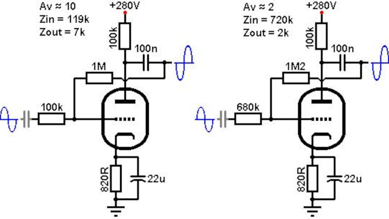
Negative feedback is a pretty simple idea: subtract a little of the amplifier’s output from the input. It reduces the amplifier’s gain with a flat response, so it’s useful for removing humps in the frequency response and reducing the tendency for distortion. In a single-ended triode amp it’s done with a resistor and capacitor from anode to grid, but the question is, just what resistor or capacitor?. Here the page has all the answers, taking the reader through calculating the desired gain, and picking the value of the capacitor to avoid affecting the frequency response. We wish that someone had taught us this three decades ago!
The website is full of really useful info about valve or tube amps, and it’s worth mentioning that he’s made it available in book format too. There’s no reason not to have a go at vacuum electronics. Meanwhile in case you are wondering what project prompted this, it was a quest to improve upon this cheap Chinese kit amplifier.


This article is misleading, it omits the grid-leak resistor required for biasing the tube. This resistor is in the same range as the feedback resistor, so it cannot be ignored in the calculations. In the tube era, local “voltage feedback” was rarely used becaus of its many disadvantages. “Current feedback” a.k.a. “cathode degenerative feedback” is the common way to set the stage gain, some data sheets even provide tables with recommended resistance values and associated performance data.
The guys who made tubes also provided a lot of literature, most notably RCA’s “Radiotron Designer’s Handbook” (available at archive.org) and Philips’ “Series of books on electronic valves” ( https://frank.pocnet.net/other/Philips/SeriesOnElectronTubes.html ).
A grid-leak is not the only way to bias the stage. Merlin’s book touches on different bias methods.
Also, please note that his book and the linked article are targeted towards guitar amplifier stages so they might not be generally applicable and the disadvantages of voltage feedback might not matter here.
What kind of guitar amp, though ?
A real, clean one or the usual “distortioner” ?
There were not few fans of the distorted, broken sound. Like circuit-bending.
Hi Joshua,
good point! Tubes can be operated the less linear region. This does not by nature make them sound soft and nice. It depends on the harmonics.
The referenced web page seems to be a starter at the first glimpse, but there is so much more!
Push Pull vs Single Ended, SPRR, etc. I recommend checking out http://www.tubecad.com . John Broskie is doing a great job there explaining details and concepts – since decades!
Use the articles references as a starter and dig in deeper! Tubes are amazing. And bear in mind: you might not want a perfect clinical reproduction to be pleased!
Greetings
GvTT
More music has been made with “distortioner” amps that has really touched people, than “a real, clean” amps. The greater audience does not give a damn if the amp distorts or not, as long as it sounds nice to their ears. Firstly, you’d need to define what “clean” means in this context. With tube, or valve, amps the border between clean and distortion is pretty hazy.
Not into guitar amps, but are there any that can user-selectively simulate the “tube sound” via a pickup-ADC-processing-DAC method?
Without a usually high-impedance DC path between grid and cathode the grid would accumulate negative charge and block the tube. This goes for all biasing methods. If a circuit appears to work with a floating grid, there’s something wrong, like a leaky capacitor, a dirty socket or a tube damaged by severe overloading.
This is not correct. The tube may not necessarily become blocked. Besides the images are represented out of full context. Typically there would be an interstage attenuator or volume control.
True. Starting with regular amplifier stage, and just omitting cathode capacitor would be a good start. Then vary the value of cathode resistor to get the needed gain.
Which is exactly what you do with single transistor amplifiers to get approximately A = -Rc/Re.
I don’t want to troll, but that’s a shitty university if you didn’t learn basic analogue circuit design. It being a vacuum tube circuit doesn’t make much of a difference, negative feedback is negative feedback
“negative feedback is negative feedback”
Sez Ms. Pot to Mr. Kettle.
I don’t know if that’s a cultural reference, but it went right over my head, lol.
Happy new year to all btw
On the off chance you’re not a native anglophone and aren’t familiar with the reference: this is a short form of the expression “the pot calling the kettle black”, to accuse someone of something that you’re guilty of yourself. Amusingly (if your username is any guide), the phrase comes from a 1620 English translation of a line from Don Quixote: “Dijo el sartén a la caldera, Quítate allá ojinegra.”
What’s also relevant here is that electron tubes do give a more fundamental understanding to electronics.
The current flows from negative (cathode) to positive (anode), like its the case with the physical current direction.
The cathode, being heated up by the heather) does emit the electrons and then they get attracted by the cathode. That’s just natural, not the abstract concept with transistors and their holes.
So they should still be teached on paper, at least.
*attracted by the anode, of course. Silly auto-correction. 😂
They are not so very different. Tube cathode does not magically “create” electrons, they come from the negative side of power supply. Heating the cathode just helps the electrons jump out of the cathode surface. An NPN transistor emitter works exactly like that, only it does not need heating because it is not “unconnected” in vacuum.
Actually you can have power generated from a hot cathode. Its called Thermionic Energy Generation.
http://large.stanford.edu/courses/2018/ph240/swifter2/
This effect also allows a Hartley circuit to oscillate with an anode supply of zero volts. It’s an old lab curiosity that can drive the uninitiated mad searching for ghosts.
It was vacuum technology they never taught us, not negative feedback. TBH a school that retained that course in the early 90s would have been a shitty one, not the other way round.
They’ve whittled it down even further. Today they don’t even teach bipolar transistors.
Today we have 4-5th year students in engineering who haven’t completed a single course in analog circuit design. There’s the basic mandatory physics that gloss over Ohm’s and Kirchoff’s laws and some circuit analysis, but I find that 80-90% of students don’t remember any of it. They can’t calculate a simple resistor circuit, or understand its applications.
It’s frustrating when they land on an advanced course that deals with among other things, analog signal feedback and amplification, and we have to teach them remedial high-school level electronics just so they can keep up with the material. They’re so much behind that even as they pass the course, learning just that needle-thin wedge of special knowledge required to pass the exam, they will never be able to apply the knowledge in the real world.
I graduated in 1970 without hearing any prof mentioning tube technology. I spent the next 40 years designing, building, and testing high power radar transmitters with traveling wave tubes, klystrons, magnetrons, thyratrons, …. etc.
The circuits depicted here are FX loop return stages. Valve Wizard goes into LNFB in a more broad sense but this circuit was originally discussed in the ‘The Ultimate Tone’ (Kevin O’Conner, 1995) as an effects return stage. The LNFB is meant to stabilize the gain to account for varying drive levels coming from external effects units as well as helping to preserve the overall fidelity of the effected sound. What’s not shown however is the series/parallel virtual earth mixer that preceded it so it looks like there’s no grid-leak to ground when in the original it was provided by the effects send and return level pots; if there’s a post FX-loop master volume pot after the return stage, that’s also a grounding point.
The circuits in the write up will simply not work. The gate is not correctly biased. Without this the rest of the writeup is simply not very relevant and does not teach anyone how to setup a vacuum tube circuit.