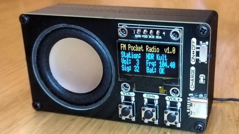
The FM broadcast band has been with us since the middle of the 20th century, and despite many tries to unseat it, remains a decent quality way to pick up your local stations. It used to be that building an FM broadcast receiver required a bit of RF know-how, but the arrival of all-in-one receiver chips has made that part a simple enough case of including a part. That’s not to say that building a good quality FM broadcast receiver in 2024 doesn’t involve some kind of challenge though, and it’s one that [Stefan Wagner] has risen to admirably with his little unit.
Doing the RF part is an RDA5807MP single chip radio, but we’d say the center of this is the CH32V003 RISC-V microcontroller and its software. Twiddling the dial is a thing of the past, with a color display and all the computerized features you’d expect. Rounding it off in the 3D printed case is a small speaker and a Li-Po pouch cell with associated circuitry. This really is the equal of any commercially produced portable radio, and better than many.
Even with the all-in-one chips, there’s still fun in experimenting with FM the old way.


Yet another nice-looking/well documented project…. without the hardware source. Only the pdf/gerber. Of course nobody is obliged to whatever. But I’m still amazed at how that’s a common practice in the hardware world.
Also I dont see the point of documenting, provididing the sofware, … and not the schematic source files.
That’s an oddly entitled way of looking at it. I don’t understand why anyone would ever complain about getting only a visual representation of the schematic when that’s the truest form of source to a real hacker. If someone really wants it in a proprietary format which requires a specific software package to manipulate, then if they can read a schematic (this is ‘hackaday’) they will recognize and appreciate that they have already been given everything necessary to create it for themself. I don’t see the point in complaining about not getting more after being given all which is needed.
I surely wouldn’t want the proprietary format, i couldn’t read it. And you right about it.
But those projects typically use kicad or (like this one) easyEDA. That’s nothing proprietary, and very useful for hackers.
Then just ask if it’s available (nicely) instead of … Whatever you think this purity testing nonsense is.
Learn to dig a little: He has the schematic right here:
https://github.com/wagiminator/CH32V003-FM-Receiver/blob/main/documentation/FM_Radio_Receiver_wiring.png
That’s the same as the pdf, not what I call the ‘source’. Not something a hacker (this is ‘hackaday’) can use, peruse, modify, tinker with. You might, also, be slightly less rude.
It’s a strange choice to put the USB connector and the slide switch on top side of the PCB without any cover. I would have made an extra front panel pcb to cover them in a way like Bobricius does. An alternative would be to put the USB connector and the slide switch on the bottom side, but that still leaves the tactile switches unprotected.
Indeed some protective front panel would be a good idea. The way it is now is asking for trouble om a cold winter day wearing a fleece sweater. One good ESD zappp and the display or other IO function stops working. On the other hand, if this doesn’t happen and the user is a carefully person who never drops anything, ir might last for years to come.
Either way a fun project based on some very cool IC.
How do you define “source”??
He has a gerber, the BOM, and a schematic – what more do you need to tinker with it??
If I need more info on a chip or how it works / how to use it, I google the part number or plug it into FINDCHIPS.COM and read the spec sheet.
That’s weird, i didn’t expect people to not understand ‘source’. I mean the EDA files used to create the pdf/png. It’s like when writing a text with a word editor, and you only provide the PDF output : you can’t modify the text, or you have to write it all again from the pdf. The source in this analogy is the word processor original document. For schematics thats’ the kicad projects files, or easyEDA or whatever is used. If the EDA is proprietary, then yes, the PDF/PNG is what’s most useful. Not the case here though.
I understand something different by “source”, too.
A source is a reference to something that supports your claims.
In German, it’s “Quellenangabe” or “Quellennachweis”.
It’s a source of information you used for writing your essay in school, for example.
Like, for example, Wikipedia or Encyclopædia Britannica.
The full English term is “source citation”, it seems.
Or also “list of references”, “list of sources” etc.
What you’re referring to would be a source file, I guess.
@joshua, you probably right. I’m a software developer and probably biaised here …
There’s a link on the GitHub page that says “EasyEDA Design Files”, is that not what you’re looking for?
@eddie
Yes, you right. So much for digging. The link goes to the main page @oshwlab for the author, but you can find the project in menus (https://oshwlab.com/wagiminator/ch32v003-fm-radio-receiver) and then at the end of the page there’s a button “open in editor”.
Thx !
Get a grip, you are the rude one here. The designer owes you nothing, yet already provided the design, just not in your preferred format? That is not reasonable to gripe about.
Nice project. It really is amazing how the capability of modern electronics has shot up, while the price and parts-count have decreased by so much.
This is now out of context because mods deleted the comment that you and I replied to.
Volume buttons split by channel up, and no down at all. What a downer if you want to go back between 2 stations? These toy FM radio chips become just a novelty when you have to go up only.
The RDA5807M datasheet says otherwise: the chip has a channel mode with selectable spacing down to 25 kHz, but also a direct mode where the frequency is set as a 16 bit value in register 0x08.
CH+ should be SEEK on/off, with a rotary encoder for direct frequency selection.. maybe with an A1333.
I really like that they included a few of their equations in their schematic for the high pass filter, gain, and current limit for the battery charger. Inspiring to see completed projects and it’s nice to be exposed to a few new components I wouldn’t have looked at normally!
“Twiddling the dial is a thing of the past”
I will be twiddling my knob for years to come, and that’s the way I like it!
To be honest, “the push a button to search for the next channel” never lands exactly on the correct freq, and if you have any tuning options it is usualy a shortpress for “up” and no means ro go a step down.
It is a shitty system that is barely good enough for consumers, and not at all good enough for me.
But on the other hand, their weak signal recieve is usually pretty shit anyway, so stopping the scan somewhere around the strongest signal is usually enough
Guarantee that screen will crack the first time it falls on its face. Those ones are so fragile.
WA-SMSI or WP-SMBU series parts would make it easy to place all parts on the front PCB bottom side, recessing the panel in a matching cutout. One could even make the front panel entirely clean by adding four such terminals in the corners, and pull the PCB into its enclosure from the rear.
“Twiddling the dial is a thing of the past”
And if it’s not, rotary encoder mod for this project should be possible.