An amber on black interface on a green reproduction Game Boy screen. It has the FM station 88.9 in large letters in the middle of the display and "Ice Cream (Pay Phone) by Black Pumas" displayed in a box below. A volume indicator is on the left side of the tuner numbers and various status icons are along the top of the screen. A paper cutout of an orange is next to the Game Boy on a piece of paper with the words "Orange FM Prototype" written underneath.

Orange FM Brings Radio To The GameBoy

We’ve all been there. You left your Walkman at home and only have your trusty Game Boy. You want to take a break and just listen to some tunes. What to do? [orangeglo] has the answer now with the Orange FM cartridge.

This prototype cart features an onboard antenna or can also use the 3.5 mm headphone/antenna port on the cartridge to boost reception with either a dedicated antenna or a set of headphones. Frequencies supported are 64 – 108 Mhz, and spacing can be set for 100 or 200 kHz to accomodate most FM broadcasts setups around the world.

Older Game Boys can support audio through the device itself, but Advances will need to use the audio port on the cartridge. The Super Game Boy can pipe audio to your TV though, which seems like a delightfully Rube Goldberg-ian way to listen to the radio. Did we mention it also supports RDS, so you’ll know what that catchy tune is? Try that FM Walkman!

Can’t decide between this and your other carts? Try this revolving multi-cart solution. Have a Game Boy that needs some restoration? If it’s due to electrolyte damage, maybe start here?

Continue reading “Orange FM Brings Radio To The GameBoy”

A Very 21st Century Receiver For A Very 20th Century Band

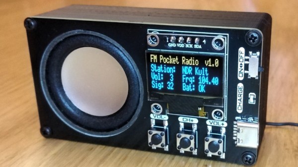
The FM broadcast band has been with us since the middle of the 20th century, and despite many tries to unseat it, remains a decent quality way to pick up your local stations. It used to be that building an FM broadcast receiver required a bit of RF know-how, but the arrival of all-in-one receiver chips has made that part a simple enough case of including a part. That’s not to say that building a good quality FM broadcast receiver in 2024 doesn’t involve some kind of challenge though, and it’s one that [Stefan Wagner] has risen to admirably with his little unit.

Doing the RF part is an RDA5807MP single chip radio, but we’d say the center of this is the CH32V003 RISC-V microcontroller and its software. Twiddling the dial is a thing of the past, with a color display and all the computerized features you’d expect. Rounding it off in the 3D printed case is a small speaker and a Li-Po pouch cell with associated circuitry. This really is the equal of any commercially produced portable radio, and better than many.

Even with the all-in-one chips, there’s still fun in experimenting with FM the old way.

Tivoli Teardown Disappoints

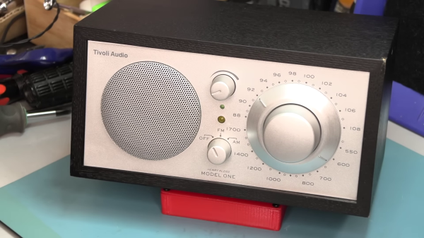
[Fran] has been curious about the innards of Tivoli Audio’s Model One radio, but was reluctant to shell out $200 just to tear it apart. But she found one recently on eBay, won the auction, and proceeded to do a review and teardown. Spoiler alert, she was disappointed.

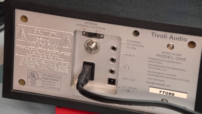
Physically speaking, the radio looks great and has quite an array of I/O connections. The geared tuning knob looks cool, but is heavily damped which [Fran] isn’t keen about. Turning it on, a few more quirks are discovered. The volume control is out-of-whack — it appears they substituted a linear taper potentiometer where a logarithmic taper was called for.

Another problem, at least in the RF-dense metropolitan areas like Philadelphia, is the FM tuner’s station-lock feature. It is so strong that it can be impossible to tune in weak stations. This is especially ironic since, according to Wikipedia, that was one of audio engineer Henry Kloss’s main goals when founding Tivoli Audio back in 2000:

Their first product was the Model One, a simple to use mid-century modern designed table top radio with a high-performance tuner, receiving FM radio in congested urban locations, while maintaining the ability to pick out distant or low power stations. Kloss had noted that the mid 60’s wave of Japanese radios lacked the ability to receive FM stations in congested locations, and this became a defining goal of his radio designs throughout his career.

Interestingly, many folks in the YouTube comments say their Model One radios have none of these issues. We wonder if [Fran] has obtained a damaged radio, or maybe a newer version produced with less attention to detail. If you have a broken Model One radio, before tossing it, consider the hack we wrote about last year, turning it into an internet radio.

Continue reading “Tivoli Teardown Disappoints”

Working With I2S-Compatible FM Tuners

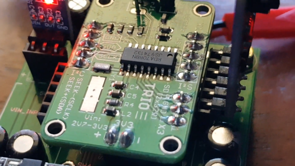
While the Internet is a great place to get access to any music or audio you can dream of, there’s still a place for broadcast radio. [mit41301] has recently been exploring implementing a simple FM tuner chip in various projects.

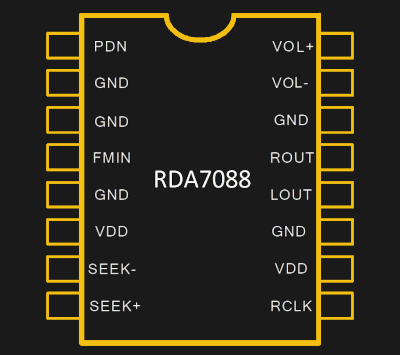
The chip in question is the RDA7088, which is designed to require the bare minimum in external components, and is available in a compact SOP16 package. As per the datasheet, it was intended for use in applications like portable radios, PDAs, cell phones, and MP3 players.

[mit41301]’s first attempt involved using the chip as a simple tuner, hooked up to a PIC10F200 for control. Investigation revealed it was capable of outputting digital audio via I2S, while being commanded via I2C. By default, it spits out audio at a low sample rate of 8 kHz, but reconfiguration will jump that up to 44.1 or 48 kHz. Piping that digital I2S stream out to a DAC then delivers analog output that can be fed to an amplifier. The build also got remote control, with the PIC handling decoding IR signals and outputting commands to the radio chip.

Following this success, [mit41301] then went further, hooking up an ESP-01 to the chip to try and get RDS going. If you’re unfamiliar with the Radio Data System, it’s a way for short textual messages to be sent out by FM broadcasters. In addition to the duties carried out by the PIC module, the ESP-01 is also charged with receiving RDS data from the RDA7088, and outputting it to a display.

While using such chips is routine in industry, it’s always great to see a DIY guide to interfacing with specific hardware. If you want to integrate FM radio into your own projects, the RDA7088 is a simple and easy way to do so. We’ve seen similar work before, adding FM radio to the Raspberry Pi.

Continue reading “Working With I2S-Compatible FM Tuners”

Ask Hackaday: What’s Going On With Mazdas In Seattle?

What hacker doesn’t love a puzzle? We have a doozy for you. According to KUOW — the NPR affiliate in Seattle — they have been getting an unusual complaint. Apparently, if you drive a Mazda made in 2016 and you tune to KUOW, your radio gets stuck on their frequency, 94.9 MHz, and you can’t change it.

According to a post from the radio station, it doesn’t just affect the FM radio. A listener named Smith reported:

“I tried rebooting it because I’ve done that in the past and nothing happened,” Smith said, “I realized I could hear NPR, but I can’t change the station, can’t use the navigation, can’t use the Bluetooth.”

Continue reading “Ask Hackaday: What’s Going On With Mazdas In Seattle?”

A Raspberry Pi next to a small circuit board

An Inexpensive FM Receiver For The Raspberry Pi

At this point, there are no shortage of impressive hacks for the Raspberry Pi. [Dilshan Jayakody] recently documented his experience in designing and building an inexpensive FM Stereo Receiver for the Pi platform, and the results are impressive.

Quite a few FM receiver projects center around the RDA5807 or TEA5767 ICs, however [Dilshan] has used the QN8035 by Quintic Corporation in his build. A handful of discrete components on a pleasing single-sided PCB is all that is needed to interface the QN8035 with the Pi’s I2C bus.

After demonstrating that the FM tuner could be, well, tuned at the command line, [Dilshan] then coded a smart looking GUI application that makes tuning a breeze. The software allows the listener to manually and automatically scan through FM stations, decode program service data, control the volume, and display the RSSI and SNR readings from the tuner.

As we reported earlier, FM radio is on a slow decline into obsolescence. This latest project isn’t aiming to break new ground, however its simplicity and inexpensive components are the perfect combination for beginner hackers and radio enthusiasts alike. More details can be found over on Hackaday.io. The schematic, source code and bill of materials can be found on GitHub.

Continue reading “An Inexpensive FM Receiver For The Raspberry Pi”

A Homebrew Radio, As All The Best Homebrew Radios Should Be

It started with an old TV sound chip, and some curiosity. The TDA1701 that [Philip Bragg] found in a box of junk is a complete FM IF strip and audio power amplifier from the golden age of analogue PAL televisions, and while it was designed for the 5.5 MHz or 6 MHz FM subcarrier of European broadcast TV, he found it worked rather well at the more usual 10.7 MHz of a radio receiver. There followed a long thread detailing the genesis bit-by-bit of a decent quality VHF radio receiver, built dead-bug-style on a piece of PCB material.

The TDA1701 was soon joined by a couple of stages of IF amplification with a ceramic filter, and then by several iterations of a JFET mixer. A varicap tuned MOSFET RF amplifier followed, and then a local oscillator. Finally it became a fully-functional FM radio, with probably far better performance than most commercial radios. He admits tuning is a little impractical though, with what appears to be a cermet preset potentiometer covering the entire band.

We suspect this project isn’t finished, and we hope he posts the schematic. But it doesn’t really matter if he doesn’t, because the value here isn’t in the design. Instead it lies in the joy of creating an ad-hoc radio just for the fun of it, and that’s something we completely understand.

We’ve covered a lot of radios in our time, and while it might be the first to feature a TV sound chip, it’s not the first built on bare PCB.