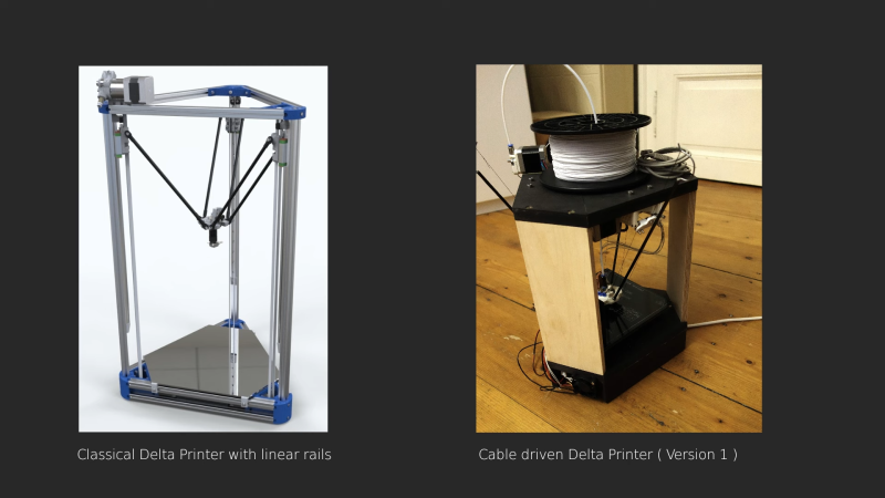
Most of us have played with a Cartesian-style 3D printer. Maybe you’ve even built a rigid delta. In this case, [Diffraction Limited] decided to a little further away from the norm with a cable-based delta design.
This delta design uses direct cable drives to control the end effector, with preloading rods effectively decoupling the preload from the drive force. Thus, the motors only have to provide enough power to move the end effector around without fighting the tension in the cables. The end effector is nice and light, because the motors remain stationary. With lightly-loaded motors and a lightweight effector, rapid accelerations are possible for faster printing. The video does a great job of explaining how the winch-based actuation system works to move the mechanism quickly and accurately. It’s a pleasure to watch the delta robot bouncing around at high speed as it executes a print.
The video notes that it was a successful build, though difficult to calibrate. The strings also wore out regularly. The truth of the matter is, delta printers are just more fun to watch at work than their less-controversial Cartesian cousins. Video after the break.


No point in a delta; too much is lost in height. CoreXY, YZ or XZ up to a practical limit (due to belt lengths), on the other hand…
That’s quite a sweeping generalisation. If you’re running a farm or in an enclosure, vertical space matters but if the printer is simply on a standard table, there will be plenty of headroom. For what I suspect is the majority of users, delta offers the best footprint efficiency.
That’s not to say deltas are without unique issues but I don’t think that particular one is significant in the majority of cases.
With this design, you don’t lose frame/build height due to the arms. However, the arms still need clearance above the frame, so it’s a tradeoff.
I don’t see the point of this in a structured delta.
has more meaning in a floating head like the hangprinter
It has even less moving mass than a “normal” delta.
It’s similar to a hang printer, but with the preloaded rods replacing the tensioning strings pulling in opposing directions.
Just a random thought, has anyone applied a delta mechanism to a laser engraver/cutter ?
Yes? I’m sure I’ve seen one somewhere.
The IVi printer on kickstarter did. And it actually worked pretty well. I have one of the prototypes, but covid struck and the project failed.
I worked on a large cable driven corexy mechanism once. It was a royal PITA to do any maintenance on it because you have to have multiple loops of cable around the drive pulleys and as soon as you release tension, the loops get scrambled. I gave up and went back to stacked belts.
I suspect the reason for the difficulty in calibrating this machine is because the angle of the cable going on/off the drive spool changes depending on position of the print head. That means the length has to change, and that means the print head is going to end up in the wrong place.
The corexy mechanism I worked on had a similar problem- the cord wound around the drive spool would walk up and down the length of the spool as the carriage moved. That changed the angle of the cable with the spool and that changed the length that was pulling at the carriage. The solution was to add a series of guide pulleys and to wind the cord on the drive pulley in fixed grooves that didn’t allow the several loops of cord to walk on the pulley. That made the maintenance problem even worse because now you had to get the loose cord onto all the pulleys just right. See: https://1.bp.blogspot.com/-bLzjjQvQpp4/W2R8jbvSaZI/AAAAAAAAWqw/W2nowqghKvo9pZCkJMqX6jVNeOXndg5dgCPcBGAYYCw/s6480/motor%2Bmount%2Brev%2B2.jpg
Cables are hard to work with.
The maker created a simulation to model most of the cable travel issues.
I think using synchromesh cables might be one way to deal with some of these issues. You would no longer need to spool the cables around the motor shaft.
I didn’t see anything in the mechanism to compensate, but maybe he does it in the firmware with a variable steps/mm depending on the effector position.
The issue with synchromesh is a huge pitch error it has. It’s not meant to be used for positioning drives (unless you close the loop), just to transfer motion with weird geometry it has to go around