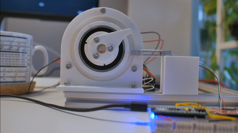
Building a 3D motor printed motor is one thing, but creating a completely custom servo motor with encoder requires some significant engineering. In the video after the break [365 Robots] takes us through the build process of a closed-loop motor with a custom optical encoder.
The motor, an axial flux design, uses a stack of 0.2mm PCBs with wedge shaped coils clamped in a 3D printed body. It’s similar to some of the other PCB motors we’ve featured, but what really sets this build apart is its custom optical encoder, which was a project in its own right. The 4-bit absolute position encoder uses IR LEDs to shine through an PCB disc with concentric gray code copper encoder rings onto IR receivers. This works because FR4, the composite material used in PCBs doesn’t block IR light.
The motor’s body was printed from ABS to withstand the heat during operation. [365 Robots] didn’t skimp on the testing either, creating a 3D printed closed-loop test stand with load cell and Arduino. Like other PCB motors it produces very little torque, roughly 2% of a typical NEMA17 stepper motor. Even so, the engineering behind this project remains impressive.


Plate style brushless motor is best at high speeds but it has very low torque. Strange decision to use such design.
Did you recognize the mug in the picture? If you are seriously into RF than you did…. Rohde& Schwarz produced them as a giveaway, it shows all the relevant unit conversions in a ruler style. Haven’t seen them in the wild for a while.
Thanks,
Now I want one. B^(
It just needs a printed harmonic drive on the output.