The Gyro Monorail: How To Make Trains Better With A Gyroscope

The gyroscopic system for gyro monorail trains that Brennan developed. (Credit: Primal Space)

Everyone who has ever handled a spinning gyroscope found themselves likely mesmerized by the way it absolutely maintains its orientation even when disturbed. Much of modern technology would be impossible without them, whether space telescopes or avionics. Yet during the early 20th century a much more radical idea was proposed for gyroscopes, one that would essentially have turned entire trains into gyroscopes. This was the concept of the Gyro Monorail, with Louis Brennan being among those who built a full-sized, working prototype in 1910, with its history and fate covered in detail by [Primal Space], along with an accompanying video.

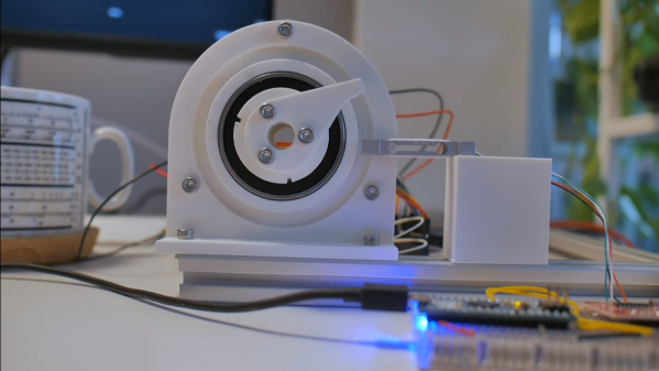
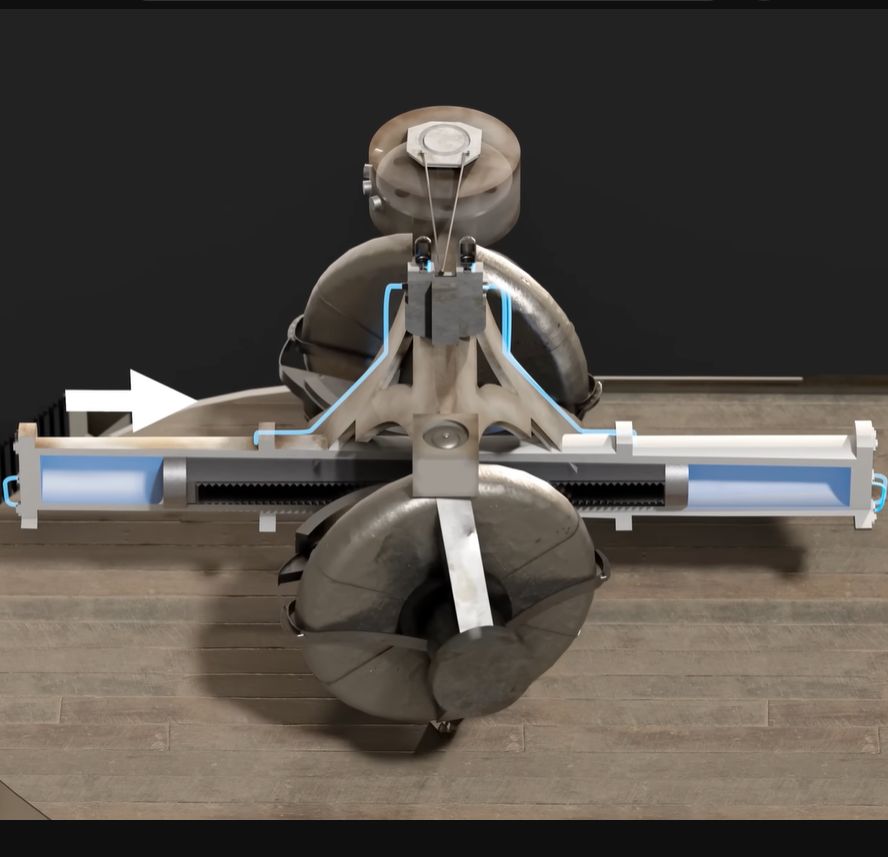
At first glance it may seem rather daft to have an entire train balancing on a single rail track, using nothing but gyroscopic forces to keep the entire contraption level and balanced even when you feel the thing should just tip over. Yet the gyroscopic system that Brennan created and patented in 1903 turned out to function really well, and reliably kept the train on its single track. Key to this was the use of two gyroscopic wheels, each spinning in an opposite direction, with a pneumatic system linked to a gear system between the two wheels that used the gyroscope’s precession in corners to quickly establish a new balance.

Despite this success, investors were unconvinced, and regular trains were already firmly established, and the system would also require that each car had its own gyro system. Even so, the idea of the gyro monorail never truly died, as evidenced by the recently created German MonoCab-OWL project. This targets converting single-rail sections into dual-rail, bi-directional service with no infrastructure investment required.

Thanks to [Stephen Walters] for the tip.

Continue reading “The Gyro Monorail: How To Make Trains Better With A Gyroscope”

Check Out These Amazing Self-Soldering Sleeves From World War II

Imagine you’re a commando, doing some big secret mission on the continent in the midst of World War II. You need to hook up some wires to your explosive charges, and time is of the essence. Do you bust out the trusty Weller and see if those petulant Axis chaps will let you plug it in somewhere? No! You use a pyrotechnic self-soldering sleeve, as [Our Own Devices] explains.

Like so many British inventions during the war, the sleeves really are ingenious. They were developed by the Special Operation Executive, an organization charged with sabotage and subversion operations in then-occupied Europe.

The soldering sleeves were designed to make electrical connections between detonators and firing wires for explosives.  The sleeves consist of a copper tube through which wires to be joined are fed, with a lump of solder in the middle. The assembly is covered in pyrotechnic material with a safety match-style starter chemical dosed on top. Using the sleeves is simple. First, two stripped wires are fed into either end of the copper tube. The starter the sleeve is then ignited using the box, just like striking a match. The pyrotechnic material then gets red hot, melting the solder and making the connection.

It’s well worth watching the video to see how these field-expedient devices actually work. We’ve explored the use of more-typical solder sleeves before, too. Video after the break.

Continue reading “Check Out These Amazing Self-Soldering Sleeves From World War II”

FLOSS Weekly Episode 768: Open Source Radio

This week Jonathan Bennett and Doc Searls talk with Tony Zeoli about Netmix and the Radio Station WordPress plugin. The story starts with the Netmix startup, one of the first places doing Internet music in the 1990s. That business did well enough to get bought out just before the Dot Com bubble burst in 2000. Today, Tony runs the Radio Station plugin, which is all about putting a station’s show schedule on a WordPress site.

In the process, the trio covers Internet radio history, the licensing complications around radio and streaming, the state of local radio, and more. Is there a long term future for radio? Does Creative Commons solve the licensing mess? Is AI going to start eating radio, too? All this and more!

Continue reading “FLOSS Weekly Episode 768: Open Source Radio”

High Caliber Engineering On A Low Torque PCB Servo Motor

Building a 3D motor printed motor is one thing, but creating a completely custom servo motor with encoder requires some significant engineering. In the video after the break [365 Robots] takes us through the build process of a closed-loop motor with a custom optical encoder.

The motor, an axial flux design, uses a stack of 0.2mm PCBs with wedge shaped coils clamped in a 3D printed body. It’s similar to some of the other PCB motors we’ve featured, but what really sets this build apart is its custom optical encoder, which was a project in its own right. The 4-bit absolute position encoder uses IR LEDs to shine through an PCB disc with concentric gray code copper encoder rings onto IR receivers. This works because FR4, the composite material used in PCBs doesn’t block IR light.

The motor’s body was printed from ABS to withstand the heat during operation. [365 Robots] didn’t skimp on the testing either, creating a 3D printed closed-loop test stand with load cell and Arduino. Like other PCB motors it produces very little torque, roughly 2% of a typical NEMA17 stepper motor. Even so, the engineering behind this project remains impressive.

Continue reading “High Caliber Engineering On A Low Torque PCB Servo Motor”

3D Mouse With 3D Printed Flexures And PCB Coils

3D mice with six degrees of freedom (6DOF) motion are highly valued by professional CAD users. However, the entry-level versions typically cost upwards of $150 and are produced by a single manufacturer. [Colton Baldridge] has created the OS3M Mouse — an open source alternative using PCB coils and 3D printed flexures.

The primary challenges in creating a 6DOF input device, similar to the 3Dconnexion Space Mouse, lie in developing a mechanical coupling that enables full range motion, and electronics capable of precisely and consistently measuring this motion. After several iterations of printed flexure combinations and trip down the finite element analysis (FEA) rabbit hole, [Colton] had a working single-piece mechanical solution.

To measure the knob’s movement accurately, [Colton] employs inductive sensing. Inductance to Digital Converters (LDCs) assess the inductive alterations across three pairs of PCB coils, each having an opposing metal disk mounted on the knob. This setup allows [Colton] to use a Stewart platform‘s kinematic model calculate the  knob’s relative position. The calculation are done on an STM32 which also acts USB HID send the position data to a computer. For the demo [Colton] created a simple C++ app to translate the position data to Solidworks API calls.

Continue reading “3D Mouse With 3D Printed Flexures And PCB Coils”

Illustrated Kristina with an IBM Model M keyboard floating between her hands.

Keebin’ With Kristina: The One With The Typewriter Orchestra

Have you ever wished you had more control over what goes into a kit keyboard build? Like, a whole lot more control? Well, that’s the idea behind the Akruvia 12×4 Playground by [iketsj].

Image by [iketsj] via YouTube

This is a 48-key ortholinear keyboard, but other than that, it’s a complete blank slate. The kit includes the PCB, diodes, RGB LEDs, and Kailh Choc V1 hot swap sockets, which is really the only choice you don’t have in the matter.

All the rest is up to you, thanks to a generous prototyping area that wraps around three sides of the keys. Bring your own microcontroller and anything else that sounds useful, like displays, rotary encoders, gesture sensors, pointing devices, you name it.
You could even magnetically link a macro pad to one side, as [iketsj] teases in the intro video. [iketsj] has made the kit available through links on their website, and you’ll find a product guide there as well.

Continue reading “Keebin’ With Kristina: The One With The Typewriter Orchestra”

Making An Aircraft Wing Work For An Audience

Many of us will have sat and idly watched the flaps and other moving parts of an airliner wing as we travel, and it’s likely that most of you will know the basics of how an aircraft wing works. But there’s more to an aircraft wing than meets the eye, which is why the Aerospace Bristol museum has an Airbus A320 wing on display. [Chris Lymas] was part of the team which turned a surplus piece of aircraft into an interactive and working exhibit, and he told the Electromagnetic Field audience all about it in his talk Using Arduinos to Resurrect an Airliner Wing.

The talk starts with an explanation of how a variable surface wing works, and then starts to talk about the control systems employed. We’re struck with the similarity to industrial robots, in that this is a a powerful and thus surprisingly dangerous machine to be close to. The various moving surfaces are moved by a series of shafts and gearboxes, driven by a DC motor. Running the show is an Arduino Mega, which has enough interfaces for all the various limit switches.

It’s fascinating to see how the moving parts in an airliner wing work up close, and we’re impressed at the scale of the parts which keep us safe as we fly. Take a look, the video is below the break.

Continue reading “Making An Aircraft Wing Work For An Audience”