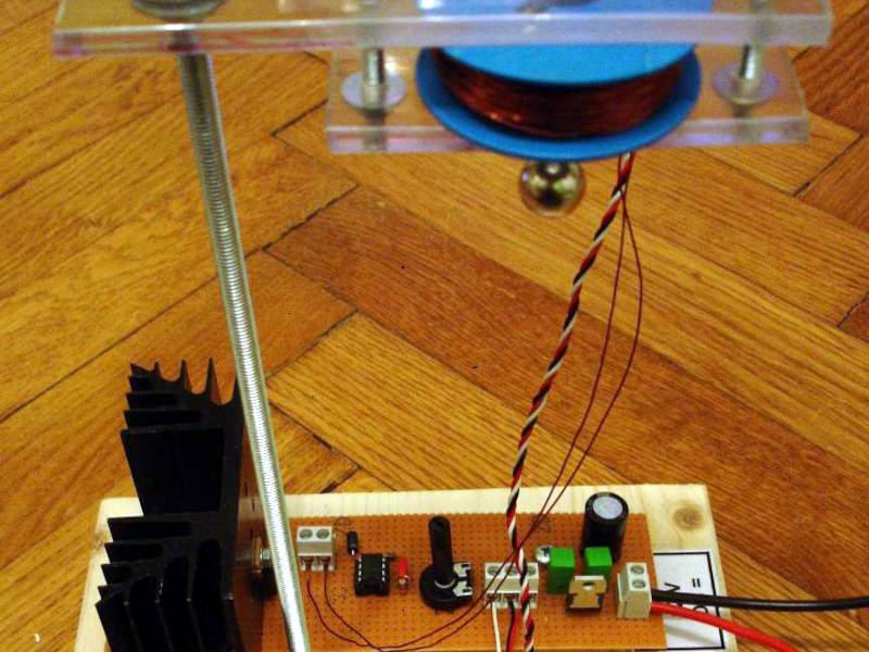
[Stoppi] always has exciting projects and, as you can see in the video below, the latest one is a very simple magnetic levitator design. The design is classic and simple: a 5 V regulator IC, a Hall effect sensor, a 741 op amp, and a MOSFET to turn the electromagnet on and off.
Sure, there are a few passive components and a diode, too, but nothing exotic. The sensor normally presents 2.5 V of output. The voltage rises or drops depending on the polarity of the magnetic field. The stronger the field, the more the voltage changes away from the 2.5 V center.
The op amp acts as a comparator with a potentiometer setting the trip point. As the ball moves up towards the coil, the voltage increases, triggering the comparator, which turns off the FET. With no current through the coil, there’s no more electromagnet, and the ball starts to fall.
Of course, as the ball falls, the voltage from the sensor also drops, and this eventually turns on the electromagnet. The ball eventually reaches a relatively stable position.
This is one of those cases where a simple analog circuit might work better than a digital one. Or make it hard on yourself and use an FPGA.


How do you get a signal out of the hall effect sensor that’s not swamped with by the electromagnet?
I was kinda wondering the same thing.
What is the sensor actually sensing? Does the location of the ball bearing itself modify the measurable field strength such that what’s being measured is a combination of the ball proximity and the output of the electromagnet? I’m just making stuff up here…
It’s detecting changes in that very magnetic field that it’s swamped in, due to the proximity of the sphere.
Yeah, and for it to work well, the coil needs to be an air coil. Then introducing a ferromagnetic object causes a change in magnetic flux.
This is not true, I have seen many iron core coils in this application.
And the sphere is a neo magnet not a steel ball.
The hall is not swamped, it’s in a balanced state with the sphere neo magnet.
I want to give this a try. So after reading the comments I will wait until those smarter than I hash it out some more. That way it helps keep the purchase of parts that won’t be needed down. A few years back what I now call unnecessary parts and costs I would have called my stash. How times have changed.
An air coil will make a field about 1 thousandth that of an iron core, forget about it. There is no problem. A linear Hall sensor eg 49E puts out 2.5V+/- 1.9mV/Gauss and 10⁴ Gauss=1T so +/-19V/T but the working fields are probably max ≈ 0.1T just as well because the sensor output is about 1V (about) to 5V (Vcc). Just be aware of the orientation etc since we want negative feedback not positive feedback. Also the sensor is between (on the pole piece) of the two attracting magnets so it has to be protected or it will get crushed most certainly. I have not built this one (yet) but I have some familiarity with various kits and so on as well as analog control circuits. With a really basic circuit the weight and strength of the supported magnet may be fairly limited, I’m guessing but I could be wrong about that.
The neo ball magnet has a bolt on it to stabilize it from rotating.
And air core is not needed, and if anything less efficient.