Electromechanical circuits using relays are mostly a lost art these days, but sometimes you get people like [Aart] who can’t resist to turn a stack of clackity-clack relays into a functional design, like in this case a clock (article in Dutch, Google Translate).
It was made using components that [Aart] had come in possession of over the years, with each salvaged part requiring the usual removal of old solder, before being mounted on prototype boards. The resulting design uses the 1 Hz time signal from a Hörz DCF77 master clock which he set up to drive a clock network in his house, as he describes in a forum post at Circuits Online (also in Dutch).
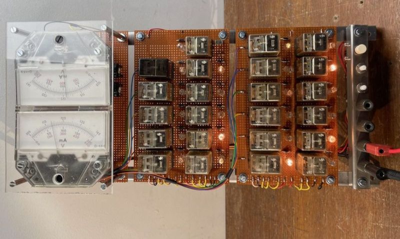
The digital pulses from this time signal are used by the relay network to create the minutes and hours count, which are read out via a resistor ladder made using 0.1% resistors that drive two analog meters, one for the minutes and the other for the hours.
Sadly, [Aart] did not draw up a schematic yet, and there are a few issues he would like to resolve regarding the meter indicators that will be put in front of the analog dials. These currently have weird transitions between sections on the hour side, and the 59 – 00 transition on the minute dial happens in the middle of the scale. But as [Aart] says, this gives the meter its own character, which is an assessment that is hard to argue with.
Thanks to [Lucas] for the tip.


The Google translate link translates from latin to english. It should translate from dutch to english : https://www-aartsite-nl.translate.goog/2024/02/11/relais-klok/?_x_tr_sl=nl&_x_tr_tl=en&_x_tr_hl=en&_x_tr_pto=wapp
Cool, thanks! I’ve also tried German, Afrikaans and Finish as a source language, just for fun.
The German translation was broken in a fun way. :D
Link updated, thanks.
I like it!
I love good ol’ DCF-77!
The DCF77 signal can be used like a pendulum, essentially.
Ideal for a post-apocalyptic world of simple homebrew tech based on crystal radios, mechanical apparata, incandescent lamps etc.
The time signal not only uses AM, but also PM for higher precision and extra information.
AM and PM modulation used on a time signal system.
I’m certain at least one German design engineer was having a sensible chuckle at that. :D
In the Late ’70, I ended up Needing a Binary Divide to a rotation of a wheel that was assembling parts in an ‘Assembly Table’.. I was built to do a Rotate Upon Decent, then Rotate Opposite Direction Back to Start on Rise.. We needed it to Rotate only on Decent, and did not care which way it rotated, but it could not rotate upon Rising..
I did the Binary Divide all in 24 VAC Ice Cube Relays..Don’t remember how I did it.. and Likely could not do it again.. HOWEVER.. Sometimes the Divide would not work.. The Only thing we could think of was Relay Switching at Line Voltage Crossing, causing things to behave Differently..
We never took it to 24 VDC to see, but we did hang big Caps on the Coil Lines and it reduced the ‘Error Rate’ to Acceptable Levels..
I would love to hear it, the click of the relays. Can you post of video of it running ?
https://www.youtube.com/watch?v=x1m-HtPIQu4
You need a schematic for a binary counter driving an R/2R network? :-)
Re: 1 Hz time signal -> It’s one pulse a minute, actually.
The forum post states ‘De klok is eigenlijk een dochterklok en loopt op de minutenpuls van het klokkennet hier in huis, dat wordt gestuurd door een vroege DCF77 moederklok van Hörz’
Translated:
The clock is a daughter clock and runs from the minute-(im)pulse from the clock-net in this house, that is being driven by an early DCF-77 mother clock from H”orz’ (I translated mother clock and daughter clock literally, but more often master clock would be used as a translation, anyway you get what i mean)
So it is one pulse per minute, not one pulse per second.
I know, I know, XKCD 386 and 356 … I got nerdsniped into ‘correcting’ this.