A Clock Made Out Of Electromechanical Relays

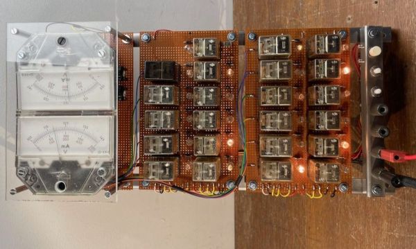
Electromechanical circuits using relays are mostly a lost art these days, but sometimes you get people like [Aart] who can’t resist to turn a stack of clackity-clack relays into a functional design, like in this case a clock (article in Dutch, Google Translate).

It was made using components that [Aart] had come in possession of over the years, with each salvaged part requiring the usual removal of old solder, before being mounted on prototype boards. The resulting design uses the 1 Hz time signal from a Hörz DCF77 master clock which he set up to drive a clock network in his house, as he describes in a forum post at Circuits Online (also in Dutch).

The digital pulses from this time signal are used by the relay network to create the minutes and hours count, which are read out via a resistor ladder made using 0.1% resistors that drive two analog meters, one for the minutes and the other for the hours.

Sadly, [Aart] did not draw up a schematic yet, and there are a few issues he would like to resolve regarding the meter indicators that will be put in front of the analog dials. These currently have weird transitions between sections on the hour side, and the 59 – 00 transition on the minute dial happens in the middle of the scale. But as [Aart] says, this gives the meter its own character, which is an assessment that is hard to argue with.

Thanks to [Lucas] for the tip.

Circle Full Of LEDs Becomes A Clock

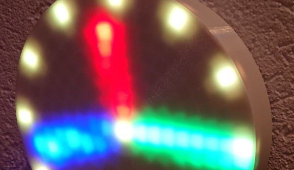
Building a clock of some sorts seems to be a time honored tradition for hackers and LED clocks seem one of the most popular. You can build anything from a seven-segment display to a binary clock or something even more fancy. [Clueless] found a circle of LED rings online and with made an LED version of an analog clock.

Continue reading “Circle Full Of LEDs Becomes A Clock”

Vintage Meters Reborn As Steam Punk Clock

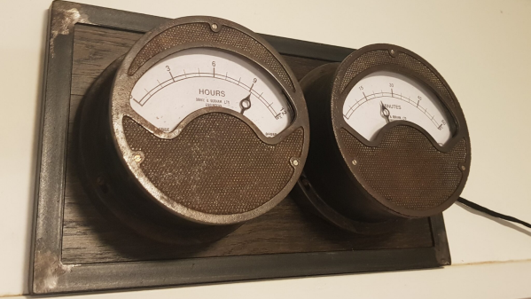
[Build Comics], purveyors of comic strips “where tools are heroes”, have saved another pair of old, vintage, analog meters from the junkyard by converting them into a Meter Clock. The real heroes of the story are their trusty tools – Mac X the knife, Mr. TS the table saw and his trusty band of clamps, G. Rinder the angle grinder, Weldy the welder, Sharp Eye the marker, rounded up by Sandy the Sander and Jiggy Saw. The Drake & Gorham (London) meters going under the knife appear similar to vintage hardware from just after the end of World War II, such as this Ferranti Ammeter found at the Science Museum Group, making them at least 75 years old.

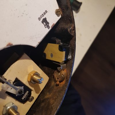
A small cam is used to engage the DST switch.

As you might expect, the conversion process is reminiscent of their previous projects. The original moving-coil movements are discarded, and the pointer is attached to a servo which will act as the new movement. Fresh dials are prepared to replace the original ampere markings with hours and minutes. To retain some of the original charm, the new dials have discoloration and blemishes replicated from the old dials.

The set screw which was once used to align the pointer with the zero mark on the dial is now used to activate a micro switch that enables daylight savings time. Two additional buttons provide a convenient interface to adjust the time. Precision time signals are derived from a DS3231 RTC module connected to an Arduino. A pair of seven segment displays are connected to the Arduino to make it easier to set the time. A piece of oak plank, surrounded by a metal angled frame, is used as a base for mounting the two meters so that the clock can be hung up on the wall.

If you’d like to build some more vintage inspired instrumentation, [Build Comics] have you covered with a Classy Weather Display or a Plant Moisture Gauge.

Continue reading “Vintage Meters Reborn As Steam Punk Clock”

Building A Giant Meta-Clock Made Of Smaller Clocks

Have any last-minute projects you finished just before the end of the decade? To help pass the time, [Erich Styger] decided to build a meta digital clock made up of 24 individual analog clocks, the perfect item to help welcome in the new year. The stepper clock is controlled by a network of LPC microcontrollers, displaying the time and room temperature, as well as several aesthetically pleasing loading animations.

Each clock operates from a 5 V USB power bank drawing less than 2 A for the full 24-clock setup. The meta-clock resides in a laser cut enclosure, with 3D printed hands telling the time. While having one board per clock would be easier to implement, [Erich] decided to use one board per four clocks arranged in rows to save on costs. The arrangement fixes the distance between clocks, though [Erich] also made the clock size slightly smaller to compensate.

The ‘stepper’ part of the stepper clock uses a 360 degree version of the VID28 stepper motor to reduce the height of the design and the cost of the project. Apart from the X12.017 driver silently driving the motors, the stepper motors also conveniently only need a ‘direction’ and ‘step’ pin, reducing the pin count needed for the microcontroller. Neodymium magnets and hall effect sensors are used for tracking the position of the hands as the clocks move, with the magnets embedded into the clock hands.

As for communication, rather than use the common I2C protocol, the more robust RS-485 was selected. A master coordinates all of the clocks using the bus, providing a command line interface. The master is also able to communicate with the host PC over USB to maintain RTC time.

During the software development phase, [Erich] made use of the SEGGER J-Link EDU mini CLI for keeping track of information about the driver and each individual stepper motor. The software controlling the motors is written in C, with boards running FreeRTOS. The stepping is handled with a timer interrupt, but because the LPC845 doesn’t have enough timer channels, all of the functionality is done within a single channel. This results in plenty of interrupt handlers, flags, and callbacks across the code, which makes for some good fun.

Speaking of clocks, check out some of our other past clock hacks, including this mini-VFD clock and this fun LED matrix clock (it lets you play Tetris!)

Continue reading “Building A Giant Meta-Clock Made Of Smaller Clocks”

Every Digital Clock Is Made Of Analog Components

In 2008, an art studio out of Stockholm released the ClockClock, a digital clock with an analog heart. The ClockClock used 24 individual analog clocks — hour and minute hands and all — to display time digitally. The world went crazy, Pinterest blew up, and everyone wanted a digital analog clock until the next interesting project distracted the masses.

This was ten years ago, and for a project that’s neck deep in stepper motors, timekeeping, and 3D printed parts, we haven’t seen a DIY project that puts these tools together to build a clone of the ClockClock. Until now, that is. [Wojtek] was inspired by the ClockClock and decided to make his own.

For the plastic bits, each of the 24 analog clocks are printed out of PLA. So far, it’s exactly what we would expect. The trick to the ClockClock is moving the hour and minute hand of each analog clock independently. This is done with a double shaft — just like a real clock — and two stepper motors. Each of the stepper motors are controlled by a single PCB in each analog clock with two 360° stepper drivers, a dual motor driver, and an ATMega328pb microcontroller. As a group, the individual analog clocks are controlled over I2C, with a single ‘satellite’ board serving as the master.

While there are a few details missing from this build, specifically how to attach the hands to the stepper motors, this is an amazing project. Someone finally built a ClockClock, and it didn’t cost thousands of dollars as the original did. You can check out some videos of the Analog/Digital clock below.

Continue reading “Every Digital Clock Is Made Of Analog Components”

LED Pendulum Pulses Out Clock Face

You have to admit [Dylan Rush’s] clock is a real swinger. Literally. You’ve seen the desk novelties where an arm with leds mounted on it sweeps out a message? [Dylan] did the same thing to make a clock but instead of drawing numbers, he actually draws an analog clock face. Y’know one of those round things with arms?

IMG_20150824_2156213_rewindBehind the clock is an Arduino driving a MAX7219 LED controller. Using the MAX7219 was a challenge because it expects a grid of LEDs while the clock needs a linear array. [Dylan] used a line of individual LEDs wired to match what the controller wanted. A rotary encoder tells the processor the position of the arm so the Arduino sketch can determine which LEDs should be lit to show the time and clock face.

What’s even more amazing is [Dylan] created this before clocks became infamous.

Swing over to the video after the break.

Continue reading “LED Pendulum Pulses Out Clock Face”

Award Clock Put To Good Use As A Bench Meter

award-clock-turned-voltage-meter

The motivation industry turns out these type of award trinkets by the millions. Here’s a way to actually put the thing to use. Instead of displaying time, the clock dial serves as the readout of a voltage meter.

When we first saw this post we assumed that the hack used some type of coil injection to drive the hands. But it turns out that this is mechanically driven. The image above shows the stepper motor which is mounted behind the clock. Its drive shaft is coupled with the adjustment knob on the back of the clock. The precision of the motor lets the PICAXE set the clock dial based on the number of motor steps. The hour hand shows the tens value with the minutes serving as ones (base 10, not base 60). This means the top measurable voltage is 12V — when the hour hand is at 12 the measurement is 0 volts plus tenths of a volt from the minute hand. With the dial taken care of the rest of the project focuses on measuring the voltage using the ADC, which has an upper limit of just 5V. This is overcome with a simple voltage divider.

After the break you can see the accuracy of the rig as it performs measurements next to a digital voltmeter.

Continue reading “Award Clock Put To Good Use As A Bench Meter”