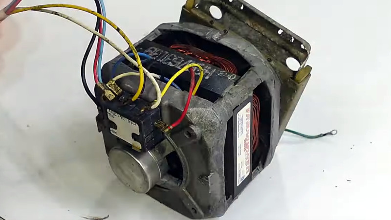
There’s great potential in salvaging a motor from a broken appliance, but so often the part in question is very specific to its application, presenting a puzzle of wires to the experimenter. This was very much the case with older washing machines and other white goods, and while their modern equivalents may have switched to more understandable motors, there are still plenty of the older ones to be had. [Matthias random stuff] sheds a bit of light on how these motors worked, by means of a 1980s Maytag washing machine motor.
Many of us will be used to old-style induction motors, in which two windings were fed out of phase via a large capacitor. This one doesn’t have a capacitor, instead it has a primary winding and a secondary one with a higher resistance. We’re not quite sure the explanation of the resistance contributing to a phase shift holds water, however this winding is connected in for a short time at start-up by a centrifugal switch. Even better, reversing its polarity reverses the direction of the motor.
The result is a mess of wires demystified, and a mains powered motor with a bit of strength for your projects. We’ve let a few of these motors slip through our fingers in the past, perhaps we shouldn’t have been so hasty.
This is a subject that we’ve looked at in the past.


Phase shift.
https://woodgears.ca/motors/reversing.html
This gives a more satisfying reason for the starter winding to have a noticeably different phase angle than the main winding – both the inductance and the resistance of the two windings will be made significantly different, such that the phase difference is enough to start.
https://electriciantraining.tpub.com/14177/css/Resistance-Start-97.htm
There’s another excellent Youtube channel that covers this issue (this channel has a bunch of related and similar videos that I recommend checking out if you are trying to do this): https://www.youtube.com/watch?v=ZKodxGcRSnw
I know who that was going to be before clicking on it and was happily surprised anyway. He’s an amazing science communicator and I enjoy his videos very much. Good recommendataion!
When you said that, I immediately thought of this guy. https://r.mtdv.me/videos/motor-hacks
Well, recently the dead washing machine of friends of mine died and I was really happy to get the motor, but it turned out it is no longer an universal motor rather than a 3 phase asynchronous machine. 230V and like 700W, I decided to keep it anyways since VFDs are quite cheap now, you never know when you need a fast motor.
Are you sure it an asynchronous motor?
One of the washing machine motors I have is a PMSM motor. If you can’t see the rotor, you can easily distinguish them by runnin a low current though one of the windings. With an asynchronous motor you will only experience drag when attempting to rotate the rotor. with a PMSM motor, the motor will have distinct “preference positions” because of the permanent magnets in the rotor.
My recently harvested motor–from a GE washer–is a BLDC. It kept the motor and the control module. My old dishwasher had a BLDC as well–didn’t think to keep the control module with that one.
My 2002 Kenmore washer (made by Whirlpool and similar to many other bands of that era) uses a PSC (permanent split capacitor) motor. There are two main coils in the motor, each around 6 Ohms DC resistance and physically large external air core inductor of about 10 turns of wire about 10 cm in diameter in series with a capacitor the controller board has two trials, one to connect the main windings and a second to cut the LC circuit in and out. This makes it possible to reverse the motor at will.
When I first got the washer, I suspected a BLDC motor because there is stepper motor like humming as the machine agitates. The humming apparently is from the clogged drive belt.
The Whirlpool design is pretty clever and minimizes the complexity of the controller. A PSC motor is a good choice for a washer where high control precision is not necessary.
That should say “two triacs” above, spell check nuked it.
The resistance reduces the phase angle of the current in the start winding so that there’s some difference in angle between the run and start fields which drags the rotor along to start the motor. (Yes, this means the resistance must be dropping a large share of the voltage relative to the inductance, and the overall impedance of the start winding must be quite low to still get enough field magnitude, so it draws quite a large quantity of current.)
Remember that in any pure reactance (perfect capacitor or inductor), the current and voltage will be exactly in quadrature (90° phase, one direction or the other depending whether it’s inductive or capacitive). Any resistance (in series or in parallel) constitutes energy loss and draws the phase away from 90° toward 0°. If the impedance were purely resistive, the current and voltage would be precisely in phase and the entirety of the volt-ampere product in the circuit is dissipated as heat, whereas it is stored and released with no loss in a pure reactance.
In a real-life motor winding, there is always a quantity of resistance, and thus the true phase angle of the current in that winding must necessarily be something less than 90° (else it would have to be a superconductor). If we’re clever and we set up one efficient winding with a lot of inductance and very little resistance, its phase angle might be some 70° to 80°. Alongside that, have another winding (displaced in angle relative to the rotor of course) with a lot less turns (less inductance) and considerably thinner wire to give it a lot of resistance: this might give 30° to 40° as an example. So you get somewhere between 50° and 30° difference in our example, which is enough to produce a reasonable moment of force in the rotor to get it turning.
This is an oversimplified example as it does not account for resistance due to the rotor and its motion which must necessarily count as an energy loss if it’s to be a useful motor, but it hopefully serves to clarify the concept.
Hey..
That looks like the Motor I Put on my Drill Press.. I needed to slow down the ‘Slowest Belt Speed’ So I went to the Junk Yard and Wrenched an 1180/850 RPM Motor and put it on..
35 Years later its still on.. and working..
Cap
Cap or no cap? (Cap is slang for a lie now)
What exactly did you wrench it from, if I may ask? I feel like a washing machine motor wouldn’t exactly be the best option there…
There are also bigger motors with such a design, but usually the start winding is switched out when the speed increases enough to throw some internal contacts outwards. The original motor on an old table saw of mine eventually smoked, and I think it was because the start winding was no longer getting switched out. Since it was designed only for very short duty during starting, it overheated. That’s my theory; I replaced the motor rather than completing the troubleshooting, but still have the old one in case I figure out how to rehabilitate it some day.
In Arizona, evaporative cooling used to be really common. There is a fairly big motor to turn a big blower (1/2 or 3/4 hp usually). In such a moist environment, corrosion takes its toll, and the motor usually has to be replaced every few years. One time when I was a kid (40 years ago or so), the cooler motor wouldn’t start anymore, my mom replaced it, and I kept the old one. I found that it actually would start if I gave it a spin. So I think that was the opposite failure case: the start winding was no longer connected at startup. I made a 12″ disc sander for woodworking out of that motor by strapping it down to a wooden base, cutting a disc out of steel and bolting it to a pulley that fit the motor shaft. Without the start winding, it was able to spin either direction, depending how I started it (a feature you probably couldn’t get if you bought a disc sander). But since then, all the cooler motors that I saw were the capacitor-start variety.
It’s called a split phase motor.
I have some hefty (for a hobbyist) machines in my workshop that use the start button to switch in a second winding (via a contactor). You hold the button until the motor comes up to speed, then release. I had always assumed the secoond winding was to reduce start current – They still draw between 86A-100A inrush at start though, and cause the house lights to flicker due to the V drop.
From the above it sounds like I have it wrong, and it’s all about dragging the motor into life, not start current which makes sense. I would guess that a stationary contactor in a nice clean electrical enclosure would be more reliable than a centrifugal switch, but more expensive.
I have used these too and originally had the same misconception. It’s easy to see why we got the wrong idea, with the high current startup these have.
I have a Bosch motor of an old eBike, has anybody experience in using such one?