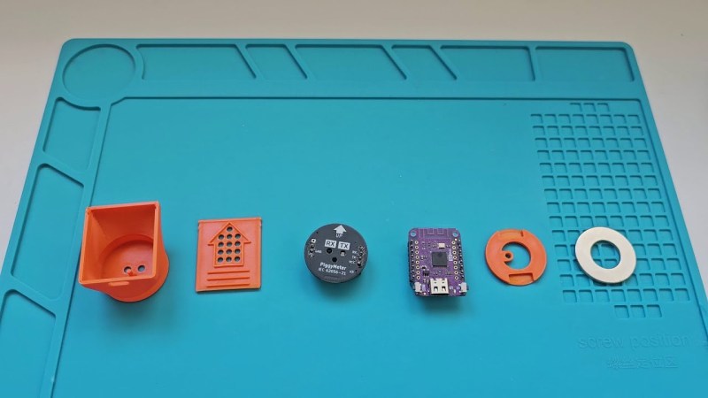
PiggyMeter is a wonderful example of a device that you never knew you needed – simple, elegant, easy to build, and accompanied by amazing documentation. It’s a snap-on interface for electric meters, dubbed so because its 3D printable shell looks like a pig nose, and it works with IEC62056-21 compliant meters. If you want to learn about your home’s power consumption in real time and your meter happens to fit the bill, look into building a PiggyMeter, it’s the kind of DIY project that a hacker was destined to design at some point.
All you need is a printed shell, a Wemos-compatible development board with an ESP32 MCU, an optical interface board, and a few small parts like a ring magnet. The optical interface board is not open source, but there’s drawings available, and the design is pretty simple, so it should be trivial to recreate. Plus, it’s also reasonably inexpensive if you don’t want to build your own board. Got parts? Simply put them all together, flash the firmware, and you have a meter adapter added to your smart home device family.
This device works with HomeAssistant, and it’s incredibly easy to set up, in part because of just how clearly everything is outlined in the blog post. Seriously, the documentation is written with love, and it shows. If you’re looking to learn how to document a device in a helpful way, take notes from the PiggyMeter. And, if you’d like to learn more about optically coupled power meter interfaces, here’s a different open source project we’ve covered before!


Where do I get the 30 x 15 x 2 mm ring magnet?
Most of modern meters also share usage over 900mhz if you have a sdr and a raspberry pi, you can get yours and likely most of the neighborhood using rtl-433 and fold it into HA using mqtt
oh it’s an optical interface to a smart meter, not “optical meter”.
Could not find the schematic or BoM for the $15 PiggyMeter board.
How does this “set new standards for documentation”? Or it’s closed-source?
If you speak German, you may want to visit the “Volkszähler” Homepage:
https://wiki.volkszaehler.org/hardware/controllers/ir-schreib-lesekopf
They have published several similar designs in the past.
Thanks for the link. The closed source board from this article looks similar to this one: https://wiki.volkszaehler.org/hardware/controllers/ir-schreib-lesekopf-ttl-ausgang
If you are looking for details, I found this post several years ago that I have been saving for a good opportunity to try replicate: https://wiki.pnpscada.com/fpost.jsp?thread=655