When you’re hooking up equipment across a vehicle, you’re often stuck sending power and data to and from things like sensors or actuators. The more wires you have to run, the more hassle, so it’s desirable to get this number as low as possible. That’s an especially big deal in the world of cycling electronics, where every additional gram is considered a drawback. To this end, companies have developed two-wire methods of sending power and data together, and now, [Keith Wakeham] has devised his own way of doing so.
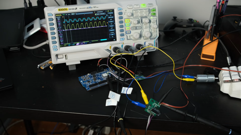
[Keith] was inspired by Shimano’s E-Tube system which is fairly fancy in its encoding schemes, but he went his own way. His concept relied on old-school On-Off Keying methods to take a signal and capacitively couple a signal into power lines. He explains the theory behind the method, and shares schematics that can be used to actually communicate over power lines. Then, he shows off the real hardware that he built to test the concept for himself.
The results? Good! [Keith] was able to maintain speeds of 57,600 bits/second even with an electrically-noisy gear motor operating on the lines. That’s more then enough for all kinds of applications.
If you’ve got your own data-over-powerline hacks, don’t hesitate to let us know.


I’ve done this as well, based on some old EE article, but there are a few things to note:
1. You want really low reverse leakage current on the diodes that lead into the peak/average detector. There are plenty of Schottkys out there that have pretty high reverse leakage, and given how small the currents are (it’s a 100 pF cap after all) you can’t afford it. The lower it is, the faster you can make those transitions. The ones he’s using are fine, but you can *easily* substitute it for something wrong.
2. You want a high-ish value resistor to ground on the floating node after the AC cap before the diodes. That node can basically sit anywhere between -0.4 and 0.4V freely, which can lead to weird data-dependent behavior. You’re essentially setting an RC highpass on the carrier. Actually giving that value a DC operating point also lets you simulate the circuit properly (obviously you need to put a load on the DC/comms path too).
3. You want to bias the transmit path at VCC/2 – so like, after his series resistor on the TX path you want some high-value resistors to VCC and GND. Helps with the initial behavior, since if the line’s been sitting idle for a while that first transition “up” is big.
Tends to work even without these (except the low reverse-leakage current diodes, that’s necessary) but can be sensitive to data patterns and temperature variation. The exact ‘value’ of the resistors I’m mentioning are in the 10-50k range, but it’s best to mess around with simulation and experiment to figure it out.
Yeah, he’s referring to the same article I used, although he doesn’t link it (“I found it on the Internet”).
It’s here: https://www.electronicdesign.com/technologies/communications/article/21799727/simple-circuit-communicates-over-low-voltage-power-lines
could try IR 38Khz modulation onto DC
Chassis as one of the wires.
Carbon fiber chassis… At least on bicycles that is electronic shifting.I don’t think the epoxy part is usually all too conductive.
You could always make your own bike and use a conductive epoxy for the areas you want to use as terminal points.
Except epoxy choice will be based on physical performance and mass at this level.
It’s easier, less expensive, and lighter to just use the correct epoxy and add the mass of 1 more wire.
Remember that at this level people are swapping out steel parts for titanium or aluminum to save grams.
(It was always ‘fun’ to work on bikes that used titanium screws filed short with JUST enough threads left to catch. And aluminum screws suck…)
i agree it’s tempting but even if it’s a steel frame, the front fork / handlebars is pretty loosely coupled to the bicycle frame. the frame is basically resting on a greased ball bearing ring on the fork. i wouldn’t count on it being conductive or non-conductive. the seatpost is in a little better condition as a conductor but it still often has a thin layer of grease and i don’t know if you could really count on it conducting or not.
on top of that, everywhere you want to install a node, you’d have to sand through the paint. ugh.
really, though, i think the premise is silly. i think 2-wire and even 1-wire networking is “cool” but the simple fact of the matter is that the data wires in like an off-the-shelf USB cable are already so thin as to be irrelevant. once you put a suitably-durable sheath on it, you’d be hard-pressed to tell the difference between a 2-power and a 2-power+2-data bundle.
but i don’t like gram-shaving on bikes anyways :)
The screws threaded in to make terminal connections will mass more than he wire anyway.
Unless people are soldering directly to the frame…
Hi,
how about greasing the ball bearing ring on the fork with supposedly conducting graphite powder instead?
Than enough.
+1
The DCC protocol, used for model trains, also works very well with noisy DC motors in the vicinity. :)
57600bps is great. But I don’t see any application that needs more than the 8000bps that DCC can provide.
The thing with DCC is that you can buy all the necessary modules ready to use. And they are *small* modules, because they need to be put inside the model trains.
Just pointing out.
DCC = Digital Command Control
https://en.wikipedia.org/wiki/Digital_Command_Control
+1
https://dcc-ex.com/#
https://rudysmodelrailway.wordpress.com/2015/10/15/use-an-attiny-with-usb-as-a-dcc-function-decoder/
If the bike won’t move, just set CV19 to 0 to disable consisting, and it should respond to its own address again…
POTS (plain old telephone) service provided -48V + two way voice + ring signal over a pair of wires for 150 years. The secret was a 600 ohm transformer to separate power and signal. If you use a modern RS422 chip (MAX3490) you can run 10 mbits for nearly a mile using tiny transformers.
And you could have a separate always on voice channel by putting an hf carrier on the wires. Thats how government offices were bugged with phones on the hook.
“If you use a modern RS422 chip (MAX3490) you can run 10 mbits for nearly a mile using tiny transformers.”
You still need to modulate it somehow – no matter what, you can’t push DC through. You can do the same trick with OOK signaling and a UART, but 10 Mbit/s wouldn’t be super easy that way since the carrier would need to be several multiples of that. 8b10b or Manchester would work, but both require more work to encode/decode.
The line rate limitation here actually comes from the fact that it doesn’t have either an idle or a preamble. If you add a preamble (for instance, send packets, but first, send 0, and don’t check the first byte in a packet because it’ll have a framing error) you can run this *way* faster.
Obviously POTS didn’t need to modulate since voice is already modulated. Data was multiplexed onto POTS lines using more modern frequency/modulation schemes and are obviously significantly more power-hungry (much like gigabit versus 10/100).
imagine if we could use 2 wires to supply power, full duplex audio and 1mbit data, oh wait, thats a POTS line
Any simple ICs that can handle all of the heavy lifting?
Doesn’t LIN wire / protocol supports something simmilar ?
No power over the data wire, but it has a complex auto addressing system.
10BASE-T1L can do 10 mbit over 1km while also supporting PoDL
https://www.ti.com/lit/an/snvaa25a/snvaa25a.pdf
There’s also DALI. Just to name another data over power line bus.
Yes buuuut… DALI (https://en.wikipedia.org/wiki/Digital_Addressable_Lighting_Interface ) includes a limited communications protocol, so it can’t easily be used for general device communication and it’s really low bandwidth.
2-wire data acquisition and control, and power delivery, covering several kilometers of cable length, has been used for agricultural applications for decades. It’s used for sun, wind, water sensors, valve controls, relays/power control, etc. I first encountered it in Africa in 1980, an implementation developed in Israel, and it had been in use there for years before that.
The coolest thing is it was polarity-agnostic, you just clamped any device anywhere on the wire pair, and it just worked.
Name? Link? Thanks!
From 1980. Sorry, I can’t remember the name. I’m pretty sure they didn’t have a website either :-/
It sounds like OFDM which has been around since the late 1960s.
https://en.wikipedia.org/wiki/Power-line_communication#Long_haul,_low_frequency
https://en.wikipedia.org/wiki/Orthogonal_frequency-division_multiplexing#Powerline_Technology
For a cable run of kilometers, it would need to be AC power and given it’s age, it has a low baud rate. It wasn’t uncommon for power companies to use it. https://en.wikipedia.org/wiki/Power-line_communication#Long_haul,_low_frequency
OFDM is the generic term. https://en.wikipedia.org/wiki/Orthogonal_frequency-division_multiplexing#Powerline_Technology
Heck, yes, it was AC. Some low voltage too, like 24V, and quite hefty wires: 10 ga or 8 ga, running as a twisted pair, insulated obviously. It was strung along like fence wire, but I imagine buried runs lasted longer.
The holy grail would be 12VDC at 10A along with 800kbps data.
Cough – WS2812B – cough! Ahem. Pardon me.
WS2812B has a data input and a data output line in addition to power. What being discussed here is power lines only.
I am doing something similar…..EOP… Ethernet Over Power lines with Netgear Powerline 2000. All Ethernet able devices (cameras, TVs computers) get better speed than wifi due to my Google smart home devices that are all wifi.
For all that is holy in radio, please don’t use those powerline networking devices. They’re the scourge of HF radio, making shortwave listening essentially impossible for a block around you.
I live far out in the country and have no HAMs around me. I checked with my neighbors who have satellite and they have no complaints. My house has a metal roof which tends to block a lot of rf emissions and I use the PLP2000 which emits less noise than the PLP1200 and earlier models so I think I’m good.
Also, while to late now, there is of course power over ethernet for exactly this situation. Central power distribution switch that cann be UPSed too!
That may be beneficial. Virtually every SW station that’s remotely interesting is sat upon by a shouty Chinese propaganda station.
Rinnai have a solution for their instantaneous has water heaters. There does not seem to be much information on it. It is a 12v supply with multiple drops.
It reminds me of Dallas Semiconductor’s 1-Wire interface:
https://en.wikipedia.org/wiki/1-Wire
(Answering some comments here), nearly all mid-range to high-end road bikes today have non-coductive carbon-fiber frames, as carbon fiber’s strength-to-weight ratio is so much better than that of the metals, and it doesn’t fatigue like the metals do. I’ve never gotten even 20,000 miles on a steel frame without cracking it; but my carbon-fiber Trek (same model as Lance Armstrong won his first Tour de France on) has three times that many miles on it. I’ve broken and replaced a lot of metal parts, even snapped a crank arm, but never broken carbon fiber.
Garth Wilson (giving my last name to differentiate me from the other Garth posting here)
The Dallas 1-wire protocol was the first thing that came into mind when I read the title as well.
When you read a title that includes “two wires”, you thought of the 1-wire protocol?
You can see into the Matrix. You are the chosen one. :)
To be fair, the fact that something called the “1-wire protocol” is a protocol that needs two wires is the real joke here.
The downside to bus-powered 1-wire is that it’s basically “use a diode and cap to hold up your local power and turn on and off the power to signal.” It’s fine for low-power devices, but anything high-power you don’t have a chance.
The “power+data” tricks here are all equivalent to the same way you do it in “RF land” – you use the equivalent of a bias-tee to split the bandpass into “DC-some low frequency” for power and “some low frequency – inf” for data.
If you want multiple channels for data that’s *still* easy, you just split the upper band into multiple bands – same way any RF protocol does it. What the OOK signaling is doing is taking a carrier (just some constant PWM frequency) and mixing it with your data signal (0s and 1s), because fundamentally mixing is multiplying, and multiplying by 0s and 1s is, well, on/off.
One of the nice things about this implementation is that you can clearly see where each of the passbands lies: you’ve got your carrier, your envelope detector, and a longer-term averaging effectively being used as automatic gain control.
A lot of the other tricks listed here (for instance, shoving RS422 through a transformer) only handle the *physical* method of combining power + data (which isn’t difficult) in different passbands but don’t handle the *modulation* issue to ensure that what you’re sending “fits into” its passband: if you read the TI note (TIDU993) describing power+data over RS485, they give you a nice schematic and say “oh yeah! modulate the data so it has no DC component.” Which, well, isn’t *hard* but it isn’t *trivial* either.
That modulation is the OOK signaling that’s being done here by turning on/off the carrier.
Well if using DC you can always insert data using a toroidal or ferrite transformer, DC voltage runs through one coil, while you use the second to inject data, or you could do it capacitvely
Same thing like getting internet from plugging a computer in the mains outlet, use a box that take the isp Ethernet, and uses the mains inside your house as the “internet jack” no cable other than either your ac cord or box to convert back to Ethernet
You can use one wire and ground with that if you also don’t need full duplex
Unless you use two different modulation frequency or protocol for tx and rx…
This would yield a DC signal (bias) with an am signal on top, with the zero point at ground, you take that and add fsk psk, pm or fm modulation to add noise resistance
It’s Zero point meaning the sine doesn’t cross zero volts rather it’s superimposed as a ripple with the DC rail +v being zero
Some (dis-)similar was done by the now discontinued LEGO Mindstorms sensors, running power and data over just two lines of wire.