Repairing A Gear With A Candle (and Some Epoxy)

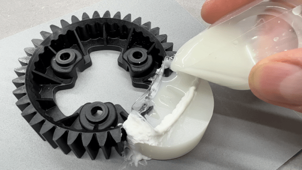
You have a broken gear you need to fix, but there’s no equivalent part available. That’s the issue [Well Done Tips] faced with a plastic gear from a lawnmower. While we’d be tempted to scan the gear, repair the damage in CAD and then 3D print a new one, we enjoyed hearing about his low-tech solution. In addition to the write up, there’s a video showing the process you can watch below.

The idea is pretty simple. Using a piece of pipe and melted candle wax, he prepared a mold of an undamaged section of the gear. Then he cast epoxy resin in place to recreate the missing pieces. There are a few tricks, like putting holes in the remaining part of the gear so the epoxy flows into the existing part. Depending on the gear’s purpose and original material, you might be able to just use it as-is. However, you could also use the repaired gear as a template to create another mold and then cast an entire gear from resin or even metal if you can cast metal.

You can argue whether resin is better or worse than PLA, but of course, it depends on the kind of resin—photopolymers are different from epoxy resins you’d use for this sort of thing. If you think you might like to make your new gear out of aluminum, you might find some inspiration in a previous post.

Continue reading “Repairing A Gear With A Candle (and Some Epoxy)”

Your Text Needs More JPEG

We’ve all been victims of bad memes on the Internet, but they’re not all just bad jokes gone wrong. Some are simply bad as a result of being copies-of-copies, as each reposter adds another layer of compression to an already lossy image format like JPEG. Compression can certainly be a benefit in areas like images and videos, but [Michal] had a bit of a fever dream imagining this process applied to text. Rather than let the idea escape, he built the Lossifizer to add JPEG-like compression to text.

JPEG compression uses a system similar to the fast Fourier transform (FFT) called the discrete cosine transform (DCT) to reduce the amount of data in an image by essentially removing some frequency information. The data lost is often not noticeable to the human eye, at least until it gets out of hand. [Michal]’s system performs the same transform on text instead, with a slider to control the “amount of JPEG” in the output text. The code for this script uses a “perceptual” character map, clustering similarly-looking and similarly-sounding characters next to each other, resembling “leet speak” from days of yore, although at high enough compression this quickly gets out of hand.

One of the quirks that [Michal] discovered is that certain AI chat bots have a much less difficult time interpreting this JPEG-ified text than a human probably would have, which provides a bit of insight into how some of these algorithms might be functioning under the hood. For some more insight into how JPEG actually works on images, we posted about a deep dive into the image format a while back.

Breadboard SDR Doesn’t Need Much

[Grug Huhler] built a simple Tayloe mixer and detector on a breadboard. He decided to extend it a bit to be a full-blown software defined radio (SDR). He then used WSJT-X to monitor FT8 signals and found that he could pick up signals from all over the world with the little breadboard system.

A Raspberry Pi Pico generates a quadrature clock that acts as the local oscillator for the radio. All the processing of the input signal to a quadrature signal is done with a 74LV4052A, which is nothing more than an analog multiplexer. In principle, the device takes a binary number from zero to three and uses it to connect a common signal to one of four channels. There are two common lines and two sets of four channels. In this case, only half of the chip is in use.

An antenna network (two resistors and a capacitor) couples the antenna to one of the common pins, and the Pi generates two square waves, 90 degrees out of phase with each other. This produces select signals in binary of 00, 01, 11, and 10. An op amp and a handful of passive components couple the resulting signals to a PC soundcard, where the software processes the data. The Pi can create clocks up to about 15 or 20 MHz easily using the PIO.

The antenna is a 20-meter-long wire outside, and that accounts for some of the radio’s success. There are several programs than can work with soundcard input like this and [Grug] shows Quisk as a general-purpose receiver. If you missed the first video explaining the Tayloe mixer design, you can catch it below the first video.

This isn’t the first breadboard SDR we’ve seen, but they all use different parts. We’ve even seen a one-bit SDR with three components total (not including the microcontroller). Seriously.

Continue reading “Breadboard SDR Doesn’t Need Much”

an analog CO2 gauge with a cute face

Cute CO2 Gauge Tells You When To Crack A Window

[Cyrill] has a good home automation scheme going: there are a number of physical switches set around the place that control the essential functions. The only problem is that in the winter time, this results in a great deal of phone checking as [Cyrill] tries to monitor the CO2 level. Tired of all this screen time, [Cyrill] set about to create an incredibly cute (and useful) Co2 monitor that plainly shows the current level and how bad it is, relatively speaking.

A large servo and an ESP32-S2 make up the guts of an analog CO2 sensor.

Behind that adorable face is a DS3225 servo being driven by a Wemos S2 mini, both of which [Cyrill] happened to have handy. Although the 25 Kg servo may be complete overkill for the situation, [Cyrill] reports that it is quieter than your average AliExpress alternatives, which makes it well worth it in our book. Then it was on to Inkscape to make the gauge itself. [Cyrill] says they’re an Inkscape noob, but that face could have fooled us.

Finally, it was time to integrate it into Home Assistant to get readings from the CO2 sensors. This was easier said than done, but [Cyrill] does a nice job of explaining how to get the ESP32-S2 up and working.

If you’re out there monitoring CO levels in your home, beware of fake sensors that cropped up during the height of the pandemic and are likely still at large.

2024 Home Sweet Home Automation: A Piano-Controlled Smart Home

There’s a scene in Willy Wonka and the Chocolate Factory where a little flap in the wall flips down to reveal a small organ embedded there. Gene Wilder plays a bit of Rachmaninoff on the organ, and the giant door to the chocolate room slowly creaks open.

Once [Nathan Orick] got this into his head, he couldn’t get it out, and had to give it a go in his own home. Regrettably there’s no chocolate rooms in the house, so he’s using various chords and melodies to do things like control the lights and the TV, as you’ll see in the video after the break. Although this one may have started as a joke of a home automation scheme, [Nathan] thinks it turned out pretty solid, and so do we.

He already had the piano and a Raspberry Pi Zero lying around, so getting this up and running was mostly about connections and code. Speaking of connections, [Nathan] was hard-pressed to find a micro-USB to USB-B cord, so he ended up splicing one together. Simple enough. The harder part was getting Linux to recognize the keyboard, but all it took was touching all the pins with a multimeter, evidently. What’s a project without a little magic?

And not only did it show up, Linux went to the trouble of registering it as a MIDI device all on its own. Once [Nathan] obtained the port number, he had data printing to the console every time he played a note. Then it was mostly a matter of writing code to interact with MIDI data and track the notes as they’re played, and put it all together with Home Assistant. Be sure to check out the brief demo after the break.

Continue reading “2024 Home Sweet Home Automation: A Piano-Controlled Smart Home”

PCB Design Review: ESP32-S3 Round LCD Board

For our next installment, I have a lovely and daring PCB submitted by one of our readers, [Vas]. This is an ESP32-S3 board that also has an onboard round TFT display, very similar to the one we used on the Vectorscope badge. The badge is self-sufficient – it has an ESP32, it has a display, a programming connector, two different QWIIC ports you could surely use as GPIOs – what’s not to love?

This is a two-layer board, and I have to admit that I seriously enjoy such designs. Managing to put a whole lot of things into two layers is quite cool in my book, and I have great fun doing so whenever I get the opportunity. There’s nothing wrong with taking up more layers than needed – in fact, if you’re concerned about emitted/received noise or you have high-speed interfaces, four-layer is the way to go. But making complex boards with two layers is a nice challenge, and, it does tend to make these boards cheaper to manufacture as a very nice bonus.

Let’s improve upon it, and support [Vas]’s design. From what I can see looking at this board, we can help [Vas] a lot with ease of assembly, perhaps even help save a hefty amount of money if they go for third-party PCBA instead of sitting down with a stencil – which you could do with this board pretty easily, since all of the components on it, save for the display, are the ones you’d expect JLCPCB to stock.

Continue reading “PCB Design Review: ESP32-S3 Round LCD Board”

Running Power And Data Over Just Two Wires

When you’re hooking up equipment across a vehicle, you’re often stuck sending power and data to and from things like sensors or actuators. The more wires you have to run, the more hassle, so it’s desirable to get this number as low as possible. That’s an especially big deal in the world of cycling electronics, where every additional gram is considered a drawback. To this end, companies have developed two-wire methods of sending power and data together, and now, [Keith Wakeham] has devised his own way of doing so.

[Keith] was inspired by Shimano’s E-Tube system which is fairly fancy in its encoding schemes, but he went his own way. His concept relied on old-school On-Off Keying methods to take a signal and capacitively couple a signal into power lines. He explains the theory behind the method, and shares schematics that can be used to actually communicate over power lines. Then, he shows off the real hardware that he built to test the concept for himself.

The results? Good! [Keith] was able to maintain speeds of 57,600 bits/second even with an electrically-noisy gear motor operating on the lines. That’s more then enough for all kinds of applications.

If you’ve got your own data-over-powerline hacks, don’t hesitate to let us know. Continue reading “Running Power And Data Over Just Two Wires”