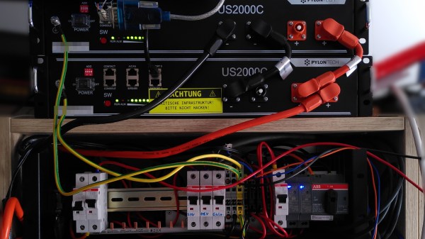
Breakers for the system on a DIN rail, with markings like 48V and 24V and 12V and so on on the bottom, and two hefty devices of some kind on the bottom, probably MPTT controllers, with hefty wires running from them.

Low-Voltage DC Network Build Incited By Solar Panels

Nowadays, some people in Europe worry about energy prices climbing, and even if all the related problems disappear overnight, we’ll no doubt be seeing some amounts of price increase. As a hacker, you’re in a good position to evaluate the energy consuming devices at your home, and maybe even do something about them. Well, [Peter] put some solar panels on his roof, but couldn’t quite figure out a decent way to legally tie them into the public grid or at least his flat’s 220V network. Naturally, a good solution was to create an independent low-voltage DC network in parallel and put a bunch of devices on it instead!

He went with 48V, since it’s a voltage that’s high enough to be efficient, easy to get equipment like DC-DCs for, safe when it comes to legal matters concerned, and overall compatible with his solar panel setup. Since then, he’s been putting devices like laptops, chargers and lamps onto the DC rail instead of having them be plugged in, and his home infrastructure, which includes a rack full of Raspberry Pi boards, has been quite content running 24/7 from the 48V rail. There’s a backup PSU from regular AC in case of overcast weather, and in case of grid power failures, two hefty LiFePO4 accumulators will run all the 48V-connected appliances for up to two and a half days.

The setup has produced and consumed 115kWh within the first two months – a hefty contribution to a hacker’s energy independence project, and there’s enough specifics in the blog post for all your inspiration needs. This project is a reminder that low-voltage DC network projects are a decent choice on a local scale – we’ve seen quite viable proof-of-concept projects done at hackercamps, but you can just build a small DC UPS if you’re only looking to dip your feet in. Perhaps, soon we’ll figure out a wall socket for such networks, too.

Improving More Leaf Design Flaws

[Daniel] was recently featured here for his work in improving the default charging mode for the Nissan Leaf electric vehicle when using the emergency/trickle charger included with the car. His work made it possible to reduce the amount of incoming power from the car, if the charging plug looked like it might not be able to handle the full 1.2 kW -3 kW that these cars draw when charging. Thanks to that work, he was able to create another upgrade for these entry-level EVs, this time addressing a major Leaf design flaw that is known as Rapidgate.

The problem that these cars have is that they still have passive thermal management for their batteries, unlike most of their competitors now. This was fine in the early ’10s when this car was one of the first all-electric cars to market, but now its design age is catching up with it. On long trips at highway speed with many rapid charges in a row the batteries can overheat easily. When this happens, the car’s charging controller will not allow the car to rapid charge any more and severely limits the charge rate even at the rapid charging stations. [Daniel] was able to tweak the charging software in order to limit the rapid charging by default, reducing it from 45 kW to 35 kW and saving a significant amount of heat during charging than is otherwise possible.

While we’d like to see Nissan actually address the design issues with their car designs while making these straighforward software changes (or at least giving Leaf owners the options that improve charging experiences) we are at least happy that there are now other electric vehicles in the market that have at least addressed the battery thermal management issues that are common with all EVs. If you do own a Leaf though, be sure to check out [Daniel]’s original project related to charging these cars.

Continue reading “Improving More Leaf Design Flaws”

A Dramatic Demo Of AC Versus DC Switching

Switches seem to be the simplest of electrical components – just two pieces of metal that can be positioned to either touch each other or not. As such it would seem that it shouldn’t matter whether a switch is used for AC or DC. While that’s an easy and understandable assumption, it can also be a dangerous one, as this demo of AC and DC switching dramatically reveals.

Using a very simple test setup, consisting of an electric heater for a load, a variac to control the voltage, and a homemade switch, [John Ward] walks us through the details of what happens when those contacts get together. With low-voltage AC, the switch contacts exhibit very little arcing, and even with the voltage cranked up all the way, little more than a brief spark can be seen on either make or break. Then [John] built a simple DC supply with a big rectifier and a couple of capacitors to smooth things out and went through the same tests. Even at a low DC voltage, the arc across the switch contacts was dramatic, particularly upon break. With the voltage cranked up to the full 240-volts of the UK mains, [John]’s switch was essentially a miniature arc welder, with predictable results as the plastic holding the contacts melted. Don your welding helmet and check out the video below.

As dramatic as the demo is, it doesn’t mean we won’t ever be seeing DC in the home. It just means that a little extra engineering is needed to make sure that all the components are up to snuff.

Continue reading “A Dramatic Demo Of AC Versus DC Switching”

Dual Brushed Motor Controller Doesn’t Care How It Receives Commands

The simple DC brushed motor is at the heart of many a robotics project. For making little toy bots that zip around the house, you can’t beat the price and simplicity of a pair of brushed motors. They’re also easy to control; you could roll your own H-bridge out of discrete transistors, or pick up one of the commonly used ICs like the L298N or L9110S.

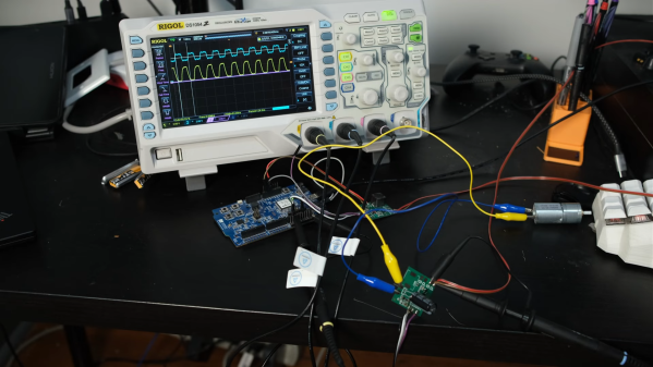
But what if you want an all-in-one solution? Something that will deliver enough current for most applications, drive dual motors, and deal with a wide range of input voltages. Most importantly, something that will talk to any kind of input source.  For his Hackaday prize entry, [Praveen Kumar] is creating a dual brushed motor controller which can handle a multitude of input types. Whether you’re using an IR remote, a Pi communicating over I2C, an analog output or Bluetooth receiver, this driver can handle them all and will automatically select the correct input source.

The board has an ATmega328p brain, so Arduino compatibility is there for easy reprogramming if needed. The mounting holes and header locations are also positioned to allow easy stacking with a Pi, and there’s a status LED too. It’s a great module that could easily find a place in a lot of builds.

If you need even more control over your brushed motor, you can soup up its capabilities by adding a PID loop for extra smarts.

Supersize DIY R/C Servos From Windscreen Wipers

We’re all familiar with the experience of buying hobby servos. The market is awash with cheap clones which have inflated specs and poor performance. Even branded servos often fail to deliver, and sometimes you just can’t get the required torque or speed from the small form factor of the typical hobby servo.

Enter [James Bruton] and his DIY RC servo from a windscreen wiper motor. Windscreen wiper motors are cheap as chips, and a classic salvage. The motor shaft is connected to a potentiometer via a pulley and some string, providing the necessary closed-loop feedback. Instead of using the traditional analog circuitry found inside a servo, an Arduino provides the brains. This means PID control can be implemented on the ‘duino, and tuned to get the best response from different load characteristics. There’s also the choice of different interfacing options: though [James]’ Arduino code accepts PWM signals for a drop-in R/C servo replacement, the addition of a microcontroller means many other input signal types and protocols are available. In fact, we recently wrote about serial bus servos and their numerous advantages.

We particularly love this because of the price barrier of industrial servomotors; sure, this kind of solution doesn’t have the precision or torque that off-the-shelf products provide, but would be sufficient for many hacks. Incidentally, this is what inspired one of our favourite open source projects: ODrive, which focuses on harnessing the power of cheap brushless motors for industrial use.

Continue reading “Supersize DIY R/C Servos From Windscreen Wipers”

Everything You Didn’t Know You Were Missing About Bias Tees

Do you need a bias tee? If you want to put a DC voltage on top of an RF signal, chances are that you do. But what exactly are bias tees, and how do they work?

If that’s your question, [W2AEW] has an answer for you with this informative video on the basics of bias tees. A bias tee allows a DC bias to be laid over an RF signal, and while that sounds like a simple job, theory and practice often deviate in the RF world. The simplest bias tee would have a capacitor in series with the RF input and output to pass AC but block DC from getting out the input, and a DC input with a series inductance to prevent RF from getting into the DC circuit. Practical circuits are slightly more complicated, and [W2AEW] covers all you need to know about how real-world bias tees are engineered. He also gives some use cases for bias tees, from sending DC signals up a feed line to control an antenna tuner or rotator to adding a DC bias to a high-speed serial line.

It’s an interesting circuit, and we learned a lot, which is par for the course with [W2AEW]’s videos. Check out some of his other offerings, like a practical guide to the mysteries of Smith charts, or his visualization of how standing waves work.

Continue reading “Everything You Didn’t Know You Were Missing About Bias Tees”

Hair Today, Gone Tomorrow, Via Electrolysis

We think of electrolysis as a way to split things like water into oxygen and hydrogen using electricity, but it has a second meaning which is to remove hair using electricity. An electrologist inserts very thin needles into each hair follicle and uses a burst of electricity to permanently remove the hair. [Abbxrdy] didn’t want to buy a cheap unit because they don’t work well and didn’t want to spend on a professional setup, so designing and building ensued.

You’ll have to read through the comments to find some build details and the schematic. The device uses commercial electrolysis needles and a DE-9 connector socket as a holder. The device can supply 6 to 22V at up to 2mA. A timer can restrict the pulse to 5 seconds or less.

Continue reading “Hair Today, Gone Tomorrow, Via Electrolysis”