Inductors are more like a resistor in series with an ideal inductor, resistors can be inductors as well, and well, capacitors aren’t just simply a capacitance in a package. Little with electronics is as plain and simple in reality as basic theory would have you believe. [Tahmid Mahbub] was measuring an electrolytic capacitor with an LCR and noticed it measuring 19 uF despite the device being rated at 470 uF. This was because such parts are usually specified at low frequencies, and at a mere 100 kHz, it was measuring way out of the specification they were expecting. [Tahmid] goes into a fair bit of detail regarding how to model the equivalent circuit of a typical electrolytic capacitor and how to determine with a bit more accuracy what to expect.
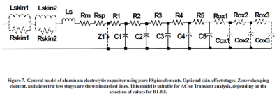
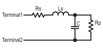
The basic equivalent circuit for a capacitor has a series resistance and inductance, which covers the connecting leads and any internal tabs on the plates. A large-valued parallel resistor models the leakage through the dielectric in series with the ideal capacitance, which is responsible for the capacitor’s self-discharge property. However, this model is still too simple for some use cases. A more interesting model, shown to the left, comprises a ladder of distributed capacitances and associated resistances that result in a progressively longer time-constant component as you move from C1 to C5. This resembles more closely the linear structure of the capacitor, with its rolled-up construction. This model is hard to use in any practical sense due to the need to determine values for the components from a physical part. Still, it is useful to understand why such capacitors perform far worse than you would expect from just a simple equivalent model that looks at the connecting leads and little else.
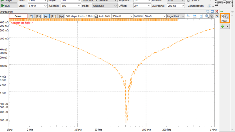
To get real answers with a practical application, if key data are not published, it is necessary to characterise your parts, which is exactly what [Tahmid] did next. Using the excellent Digilent Analog discovery tool, a measurement setup was constructed to determine the reactance versus frequency characteristic and make an estimate for the paralleled capacitance and inductance components. Straight off the screen, the reactance can dip sharply at around 40 kHz, corresponding to the self-resonance frequency. This is the frequency you need to steer well clear of if you want to get anywhere close to the specified capacitance in your application. Since [Tahmid] was designing a switched-mode buck converter, which operated around 80-200 kHz, using this part in the input circuit would be bad news – the desired 23 mVpp voltage ripple would be more like 463 mVpp, and that’s just not going to work great. Time to gently place the electrolytic parts back in the parts bin to await a different application.
The not-so-humble capacitor is a much more complicated part than it looks at first glance. Entire books have been written about them, but for a quick history tour, check this out first. Want to make your own electrolytics? No Problem. What about when they go bad?


In addition to electrolytic caps having frequency issues, they sometimes don’t develop their rated capacitance at voltages substantially below their rating (i.e. don’t use a 150 volt electrolyt in a 5 volt circuit.)
Ironically, a way to beat this is to put several smaller capacitors in parallel. A small capacitor has higher self-resonant frequency, and multiple in parallel have smaller equivalent series resistance.
[IMSAI Guy] has recently released a video where he explores the practical consequences of this subject in bypass capacitors.
https://youtu.be/BpWFGBlq0y4
Another can of worms is looking into the real performance of ceramic capacitors in smaller packages. De-rating and aging effects are something that should be considered when they are part of analog circuitry.
Type 2 ceramics (the X7Rs and Y5Vs and such) are terrible in analog applications. DC bias effect (which means nonlinear response to AC), aging, temperature sensitivity, piezoelectricity (want your capacitor to be a microphone too? too bad, it is anyway), photosensitivity (seldom discussed, try it!), and probably minor demonic possession will keep you on your toes debugging your circuits.
Yeah, it used to be that you just couldn’t use them, period, because you had almost no idea what the heck they would do. Just knowing the dielectric type doesn’t tell you what the curves look like – some are pretty flat, others are wildly terrible.
It’s gotten a *ton* better because manufacturers now have lots of simulation models and test results available, although I’m not sure any of them actually have SPICE models which handle the nonlinear stuff (I know several absolutely don’t) – and for some of them ‘small signal’ would have to be extremely small, like under 50 mV, to only have a few percent effect.
Still wouldn’t want to use them for anything high precision, obviously.
>piezoelectricity (want your capacitor to be a microphone too? too bad
A large value ceramic capacitor actually experiences tremendous compressive forces across the insulator from the charges physically squeezing the plates together, which changes the value of the capacitor depending on the voltage you apply.
So what caps *should* we use? I like ceramics because they don’t dry out like electros, and don’t fail to a short circuit if they briefly seen an overvoltage, like tantalums do.
Dave, I hate to be “that guy”. I usually don’t comment critically on the writing of an HAD article. But that first sentence hurt my head. I think it might be missing some punctuation.
“Inductors are more like a resistor in series with an ideal inductor, resistors can be inductors as well, and well, capacitors aren’t just simply a capacitance in a package.”