Why Is My 470uF Electrolytic Cap More Like 20uF?

The simple capacitor equivalent circuit taught in school

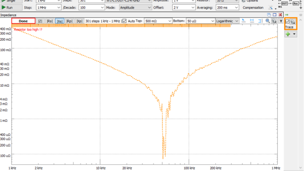
Inductors are more like a resistor in series with an ideal inductor, resistors can be inductors as well, and well, capacitors aren’t just simply a capacitance in a package. Little with electronics is as plain and simple in reality as basic theory would have you believe. [Tahmid Mahbub] was measuring an electrolytic capacitor with an LCR and noticed it measuring 19 uF despite the device being rated at 470 uF. This was because such parts are usually specified at low frequencies, and at a mere 100 kHz, it was measuring way out of the specification they were expecting. [Tahmid] goes into a fair bit of detail regarding how to model the equivalent circuit of a typical electrolytic capacitor and how to determine with a bit more accuracy what to expect.
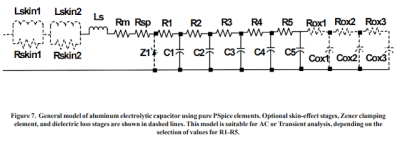
An aluminium electrolytic capacitor is more like this

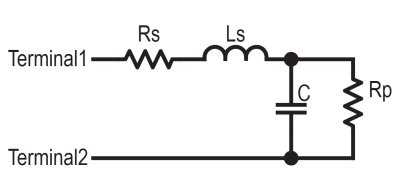
The basic equivalent circuit for a capacitor has a series resistance and inductance, which covers the connecting leads and any internal tabs on the plates. A large-valued parallel resistor models the leakage through the dielectric in series with the ideal capacitance, which is responsible for the capacitor’s self-discharge property. However, this model is still too simple for some use cases. A more interesting model, shown to the left, comprises a ladder of distributed capacitances and associated resistances that result in a progressively longer time-constant component as you move from C1 to C5. This resembles more closely the linear structure of the capacitor, with its rolled-up construction. This model is hard to use in any practical sense due to the need to determine values for the components from a physical part. Still, it is useful to understand why such capacitors perform far worse than you would expect from just a simple equivalent model that looks at the connecting leads and little else.

Continue reading “Why Is My 470uF Electrolytic Cap More Like 20uF?”

This Pogo Pin Test Fixture Keep Your SMDs From Taking Flight

There’s no denying how useful surface mount technology is, and how enabling the ability to make really small circuits has become. It comes at a price, though; most of us probably know what it’s like for the slightest wrong move to send a part the size of a grain of sand into another dimension.

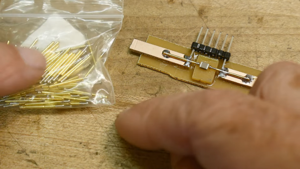
To help make testing these parts a little easier, [IMSAI Guy] has come up with this clever little SMD test fixture. It’s designed to hook up to another custom board, which in turn connects to a wonderful old Hewlett-Packard 4275A LCR meter. The jig is based on two pogo pins mounted directly across from each other on a scrap of single-clad PCB. The spring-loaded contacts, which short together when not in use, are pulled apart to load an SMD part, like the 1-μH inductors shown in the video below. The pins hold the component firmly and make good electrical contact, allowing hands-free testing without the risk of an errant touch of the test probes sending it flying.

While the test fixture works well for larger SMDs, we could see this being a bit fussy for smaller parts. That would be easy enough to fix with perhaps some 3D-printed arms that retract the pogo pins symmetrically, holding them open until the part is loaded. A centering fixture might help too, as would a clear shield to contain any parts that get the urge to go for a ride. But, for the tactical application [IMSAI Guy] has in mind, this sure seems like enough.

Just getting into surface mount? If so, you might want to check out this handy guide to the often cryptic markings used on SMD parts.

Continue reading “This Pogo Pin Test Fixture Keep Your SMDs From Taking Flight”

Agilent LCR Meter Teardown

Since 1999, one of the more popular manufacturers of test equipment has been Agilent, the spun-off former instrument division of Hewlett-Packard. From simple multimeters to fully-equipped oscilloscopes, they have been covering every corner of this particular market. And, with the help of [Kerry Wong] and his teardown of an Agilent LCR meter, we can also see that they’ve been making consistent upgrades to their equipment as well.

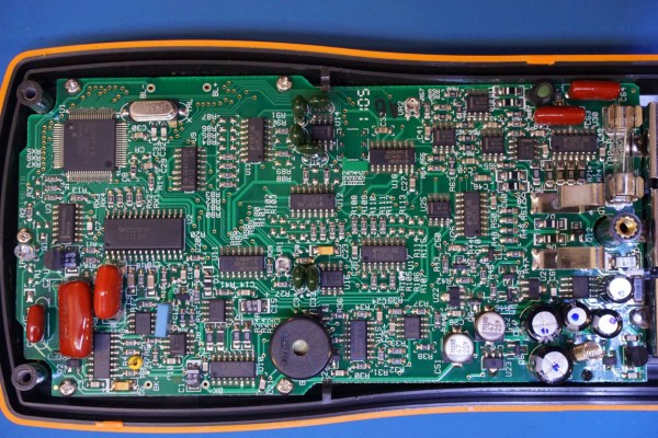
The particular meter that [Kerry] took apart was an Agilent U1731B, a capable LCR (inductance, capacitance, resistance) meter. He had needed one for himself and noted that while they’re expensive when new, they can be found at a bargain used, but that means dealing with older versions of hardware. For example, his meter uses an 8-bit ADC while the more recent U1733 series uses a 24-bit ADC. The other quality of this meter that [Kerry] made special note of was how densely populated the circuit board is, presumably to save on the design of a VLSI circuit.

While we don’t claim to stump for Agilent in any way, it’s good to know that newer releases of their equipment actually have improved hardware and aren’t just rebadged or firmware-upgraded versions of old hardware with a bigger price tag attached. Also, there wasn’t really any goal that [Kerry] had in mind besides sheer curiosity and a willingness to dive deep into electronics details, as those familiar with his other projects know already.