The problem of components not conforming to their claimed specification is one that must challenge engineers in all fields, including it seems, that of multi-rotors and remote controlled aircraft. A motor can boast an impressive spec on the website which sells it, but overheat or just not deliver when it’s on your bench. Thus [Valkyrie Workshop] has come up with a simple but ingenious rig to evaluate a motor and propeller combo without breaking the bank.
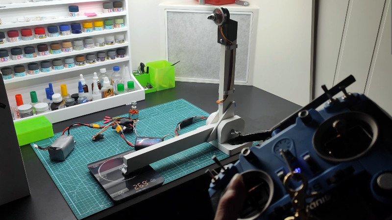
It tales the form of a L-shaped wooden bracket clamped to a pivot point at its corner with one arm pointing upwards, with motor and propeller in a 3D printed holder on the upwards arm. The other arm extends horizontally and lies on a digital kitchen scale the same distance from the pivot as the motor. The same force as is exerted by the motor is transmitted via the bracket to the kitchen scale, allowing a direct readout of the thrust in grams or kilograms. This is a first version of the rig, further work will move to a load cell and Arduino for more flexibility in measurement.
We’ve featured similar devices here in the past, including one version which can be mounted to an automobile so it can be tested at speed.


I’ve built one of these. A key design consideration is a) support many different motor mounts b) support reversing the motor for pusher configs / props. I also include a power meter so you can evaluate efficiency.
oh and if you’re worried about friction/strength vs some REALLY big motors, you can use a door hinge + 2×4 construction
I would also add a decibel meter to the setup
this method is useless for determining the performance of
high speed propellors,and is more than 105 years out of date
it measures zero airspeed thrust,which is great for hovering
but will not give any data about the characteristics at the speeds required for say a fpv drone keeping pace with an F1
car,which has been in fact done
for that kind of testing a wind tunnel that operates at the
speeds of interest,and then a balance scale rig…..as invented by the brothers Wright,105 years ago to measure airodynamic effects in moving air
Correct but will still provide some useful information. This setup measures static thrust. For dynamic thrust put the motor and prop into a wind tunnel running the appropriate velocity. Now you will achieve realistic data. In a closed loop tunnel the motor can provide its own wind. There are other positive benefits to the dynamic models. I’ll leave those for you to determine.
This method is also useless for determining the number of bears in a particular woodland park. Or the number of sunspots currently active.
It’s a static thrust test.
But they certainly get you in the right ballpark for propellers on normal-speed flying objects, and let you make informed comparisons among motors, etc.
What would be helpful are some rules of thumb in converting between results on a static test rig like this and dynamic thrust. Does anyone know of any?
I don’t think a rule of thumb conversion factor is the thing you want to look for, although this isn’t quite my field.
Considering the pitch of a propellor on an airplane, the maximum possible thrust at a given pitch angle is at a certain airspeed, and it falls off above and below that speed. Since that optimal speed can be anything, the thrust alone at 0mph isn’t enough to figure out what the thrust will be at any arbitrary other speed.
Simplifying to think of a propellor like a fan, if the incoming air is already moving fast or if the angle of the blades is very shallow, then they just can’t spin fast enough to make the air go any faster than it already is. Your engine runs out of rpm, and is basically freewheeling in the oncoming air. (If you are diving, else you can’t accelerate to that speed in the first place)
On the other hand, if the incoming air is very slow, but you have too aggressive of a pitch, you might find that the blades make so much drag that the engine hasn’t got enough torque to turn them at full speed. If the engine can’t reach full power, of course you also have worse thrust than optimal. And since propellor blades are an airfoil, you don’t want to stall it, increasing drag without improving thrust.
On a real airplane if you have variable pitch i hope you have a constant-speed prop, which just adjusts so that it gets the biggest bite of air it can at the rpm you choose to run. And then maybe you can think about the power = force * velocity equation and whether you want to figure that your thrust might be suggested by your engine power and your airspeed. I guess maybe if we go back to the brushless DC motors, logging the volts, current, and the resultant rpm and static thrust could let you figure out what you want – but not just the static thrust on its own, I would think.
Also known as static trust.
I used cut-up pizza box and adhesive tape, to make my thrust meter, for micro-sized motors and props.
Dynamic … I simply just test my plane props by flying them :) . I do static tests on the ground just to get RPM and watts to make sure we are pushing the ESC over limits…. From RPM (and pitch and length) you can get relative speed and thrust using a thrust calculator. But flying is the only way to see if meets your needs (or if you can contract with NASA for wind tunnel time). For hobbiest that might be a bit over-kill.
A mechanical lever is quicker to make then soldering some stuff together, but my preferred method would still be to mount the motor directly onto a loadcell. These things cost about EUR3, and the ubiquitous HX711 is quite cheap and easy to interface to with an uC.
I mean, technically, he is using a load cell, here! It wouldn’t take a whole lot to pop the load cell in the scale from the bracket and design your own mount for it