[limpkin] writes us to show a line injector they’ve designed. The principle is simple — if you want to measure how much PSU noise any of your electronic devices let through, known as PSRR (Power Supply Rejection Ratio), you can induce PSU noise with this board, and then measure noise on your device’s output. The board is likewise simple. A few connectors, resistors, and caps, and a single N-FET!
You do need a VNA, but once you have that, you get a chance to peek into an entire world of insights. Does that 1117 LDO actually filter out noise better than a buck regulator? Is it enough to use a Pi filter for that STM32’s ADC rail, and do the actual parts you’re using actually help with that task? How much noise does your device actually let through in the real world, after being assembled with the specific components you’ve picked? [limpkin] shows us a whole bunch of examples – putting regulators, filters and amplifiers to the test, and showing us how there’s more than meets the eye.
Everything is open source, with full files available on the blog. And, if you want it pre-assembled, tested and equipped with the CNC-milled case, you can get it on Tindie or Lektronz! Of course, even without a tool like this, you can still get good filter designs done with help of computer-aided modelling.
We thank [alfonso] for sharing this with us!


such elegant simplicity! replicating the datasheet PSRR plot of the LT3045 makes me want to replicate their setup and try some measurements of my own
+1
In my view, his method of measuring PSRR is not ideal and leads to measurement error. If an article on measuring LDO performance does not cite at least one application note from Jim Williams, it raises doubts about the author’s credibility. I understand this may seem unfair, but if he would have done a proper search on available literatur there is no way of not citing Williams. For accurate guidance on measuring PSRR (and there are tons of pitfalls!), I recommend consulting the diverse resources available from Jim Williams and Analog Devices (e.g., https://www.analog.com/en/resources/app-notes/an-159.html).
Hello Hans!
The measurement setups were inspired by application notes from the VNA manufacturer itself (omicron) and it is true I didn’t mention them. In the methods shown in the article, could you be specific on what you’d do differently?
The most obvious point is where and how you measure the input noise. It absolutely does matter if you measure directly at the input of your LDO with separate wires or – as in your case – somewhere near the input and with the same wires as you inject the noise current (inductive and resistive voltage drop). In addition there is always the danger of ground loops.
But hey, you are the expert who is even selling his stuff, not me.
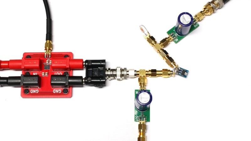
You’re mentioning a Kelvin connection. In the above picture I preferred going for short wiring with sma connections. I indeed could have added another sma connector next to the ldo input but it was already quite cramped.
The lt3045 measurement was actually made with a Kelvin connection (dedicated connectors for input/output measurements).
I didn’t mention it in the blog post, but I actually tried using transformers but found the measurements to be noisier… Perhaps I should add another paragraph about measurement setups!
It seems you know a lot, which is why I’m definitely interested to chat!
To me it looks like both the input and output are measured separately from the injection, using equivalent DC block components (the ones with the electrolytic cap).
There is a few centimeters of SMA connectors in between that and the chip. At these frequencies it seems far-fetched that it would make much of a difference.
As for bashing the stuff limpkin sells, that seems totally unnecessary and there is nothing stopping you from connecting the modules in a Kelvin connection if you prefer.
It may be appropriate to speak about “insertion loss”, wherein every passive component – splitters, fittings, couplers, etc – reduce the signal passed through the circuit. This is especially visible in RF circuits where these types of components are prevalent. Ask a Cable Guy, he knows.