When you need to make very tiny measurements, even noise in closed relays can throw you off. [Marco] was able to observe this effect and wanted to build a switch that didn’t have this problem. He found a technical paper that used rotary switches operated by stepper motors instead of relays. So he decided to try making his own version. The video below shows how it turned out.
The first part of the video talks about why relays sometimes inject a tiny voltage into a closed circuit. He then looks at costly switches that would work. However, since he needed many switches, he decided to roll his own.
While this is painful, it does let you optimize for your particular application. That’s why it was important to understand why relays don’t work well in this application. Copying part of a design from a very interesting-looking switch, custom PCB switch decks arrived in the mail.
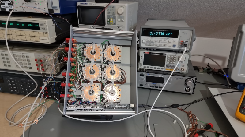
Did it work? Watch the video to find out. There was something very comforting about watching the switch rotors turn under automatic control. [Marco] reminded us that the switches look somewhat like an old auto distributor.
Measuring nanovolts isn’t for the faint of heart. With a little help, your existing gear might be able to read nanoamps, however.


Fantastic build – incredible results, superb design and quality. Nice work on the video narrative: the witty remarks sprinkled throughout the video make for many smiles throughout the otherwise efficient technical information.
Nice project. When I saw it first I was thinking about sending a tip to Hackaday, but I did not because it’s still in progress. I will follow it because I am curious about longevity of the contacts and further details.
The homing problem can be solved by making the stud longer so it intercepts the switch lever in a more sturdy location. Another possibility is to add more contacts to the PCB itself, but that would require a re-spin of the PCB. The current position of the reed switch is not a good idea. Normally the magnet is placed on the outside, and the switch (or HALL sensor) is placed in such a way there is no damage if the lever overshoots.
For the 3D printed ASA spring. Making the spring wider increases torsional stiffness. Putting it closer to the PCB also lowers the torque arm which further improves stiffness.
But overall, it looks very promising.
About a year ago I did some preliminary work on a similar project. My goal was to make a (probably) 4 stage Kelvin-Varley voltage divider for automated linearity testing of other equipment (Including a PWM based voltage reference, another project in progress) My design has a magnet on the stepper motor and uses reed relays on the PCB. I already bought some cheap 1% resistors (which have to be hand sorted) and reed contacts. The final solution was planned around higher quality resistors, and probably higher quality reed switches, but those become a significant cost quickly. I think this mechanical wiper may be a better solution. My own aims for quality are not as high as from Marco Reps. My goal is to do the best I can but while keeping an emphasis on low cost. Around 30 to 40ct for a resistor would be my limit. (A 4 stage Kelvin-Varley divider would need around 50 of them).
We _love_ stuff that’s still in progress! Don’t hesitate. :)
I get where he’s going, but it seems this has been a solved problem for decades. I’d expect COTS solutions exist, though maybe for more Euros and fewer youtube clicks.
I’m surprised a reed relay won’t do the job here.
And are mercury-wetted relays component-non-grata now or something? They were *the* way to get precision switching back in the day. Have the PC RoHS WEEE folks killed them?
As soon as you have multiple metals on the path, you easily get nanovolt level errors from thermoelectric effects. And most reed switches are non-latching, so the coil to actuate them also heats it..
There are also normally closed reed relays, but there’s still the problem of heating while the contacts are open. When the contacts close, there will be a thermal transient that decays.
Mercury relays are good for bounceless very fast switching of relatively high currents. But they are not at all low thermal EMF – which seems to be the main requirement here.
Can anyone recognize the software he uses for data visualization/logging?
You can see it at 2:15
I’ve been looking for something similar for a long time.
Grafana, though it’s just for visualization, not logging. I use a Grafana frontend for an InfluxDB database.
Many thks
Can’t the homing issue be solved by simply using an existing, or adding an additional PCB trace and detecting when the slider makes a circuit at a particular point? no external switches required.
Smaller stepper and gear drive to a more robust switch
To clarify. The switch arm should have spring forces acting equally on both sides so the shaft is not bearing side load. Moving the loading to gear supported on ball bearings would allow for miniature motors, or indeed with (as mentioned in these comments) extra traces to detect the position DC motors could be employed.
I guess it depends how fast you need to change the measurement position. Although I daresay this is more or less a solved problem if you sourced appropriate rated switches and used some gears to drive them.
Electromechanical pinball games used lots of this kind of stepping switches. The usually had a coil/solenoid and ratchet for stepping, though.
Anyone interested in precision, low level measurements should download a copy of the Keithley Low Level Measurements handbook (https://download.tek.com/document/LowLevelHandbook_7Ed.pdf). It contains a wealth of practical information on noise and error in measurement and practical advice on curing it.
I was working on MOSFET IV curves a few years ago and started by trying to measure a 100G resistor. It took about 2 weeks and multiple setups to do that reliably.
A treasured hardcopy of Low Level Measurements is on my 3-foot bookshelf(*), next to Horowitz & Hill, The Infrared Handbook, and the rubber bible.
(*) 3 feet of your most-used books, three feet from your desk. Term cribbed from Dr. Eliot’s Harvard Classics 5-foot bookshelf, updated for this century.
If it was updated for this century it would be the “one metre bookshelf”, surely?
Nice rolled Rs.
This reminds me of the stepping rotary relays used in old telephone exchanges. I’ve got a couple, they are almost solid brass, pretty robust. They step around using a ratchet and paw, with a single electromagnet for actuation. I think I used one for controlling a greenhouse and another one for sequencing Christmas decorations. Personally I’ve always preferred manual switches for decade boxes. Although I can see how automation would be preferable for some applications.
Uniaelectors
Uniselectors – typo earlier
Not an expert. Rather than dragging the contacts over the pcb, wouldn’t it be better to have them pushed down, like valves in an engine? Stepper drives a crankshaft, notches push spring loaded contacts onto the pcb.