If you’re like us, the oscilloscope on your bench is nothing special. The lower end of the market is filled with cheap but capable scopes that get the job done, as long as the job doesn’t get too far up the spectrum. That’s where fancier scopes with active probes might be required, and such things are budget-busters for mere mortals.
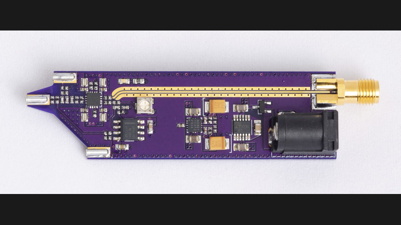
Then again, something like this open source 2 GHz active probe might be able to change the dynamics a bit. It comes to us from [James Wilson], who began tinkering with the design back in 2022. That’s when he learned about the chip at the center of this build: the BUF802. It’s a wide-bandwidth, high-input-impedance JFET buffer that seemed perfect for the job, and designed a high-impedance, low-capacitance probe covering DC to 2 GHz probe with 10:1 attenuation around it.
[James]’ blog post on the design and build reads like a lesson in high-frequency design. The specifics are a little above our pay grade, but the overall design uses both the BUF802 and an OPA140 precision op-amp. The low-offset op-amp buffers DC and lower frequencies, leaving higher frequencies to the BUF802. A lot of care was put into the four-layer PCB design, as well as ample use of simulation to make sure everything would work. Particularly interesting was the use of openEMS to tweak the width of the output trace to hit the desired 50 ohm impedance.


Any rough estimates of BOM total cost?
Chucking in only the active parts into a mouser shopping cart came to roughly 50 USD (converted from my local currency, your mileage may vary). So the whole thing could be ~60 USD with rest of the passives and PCB I guess?
Wow, this is cool! I am impressed. Maybe I want to build one myself! The corresponding Github repo even has the openEMS scripts! I always wanted to get started with openEMS, but the examples were always too far away from my day-to-day PCB problems. If I get this to run, I’ll have the proverbial foot in the door for PCB stripline simulations, etc. Thanks, James, and thanks hackaday for featuring this.
The ICs are not that expensive, as I checked on octopart. The buffer is sth like 6$ and the precision opamp is 3$.
Mind spending just a few minutes to explain what OpenEMS is / does / is for? I could Google it but I have trouble understanding these things when not explained by another maker of the same mindset.
Re OpenEMS: for those who just want to estimate trace impedance based on the cross section, atlc2 is definitely one for the tool box.
thanks! :)
That’s a really excellent writeup by [James]. Even if you’re not in the market for a high impedance 2 GHz scope probe, it’s highly recommended to read. See why ‘standard’ probes are actually pretty special, but why they fall short, and why this is needed. And then a great walkthrough of the design.
It leaves me wondering how difficult it would be to make a differential version of this.
Reminds me of Bunnie Huang article from 10 years ago https://www.bunniestudios.com/blog/2014/an-oscilloscope-module-for-novena/
ADA4817 + LMH6518
“To reduce the parasitic capacitance, an obvious move is to split a large resistor into a series combination.”
The right way to reduce the parasitic capacitance of the pads is to void the planes under the component: to do it in Stupid Detail you do a full 3D EM simulation, but you can usually get within 10-15% with a 2D field solver like ATLC.
(Voiding planes is one of those things that everyone panics about the first time they start doing GHz-scale stuff, because they’ve had “don’t split the plane!” drilled into their heads, but it’s totally normal – you’re trading off lower C for a bit higher L. Voiding the area under edge-mount SMA connectors gets you a boost of about 10-20 dB in the return loss, for instance).
“The right way to reduce the parasitic capacitance of the pads is to void the planes under the component”
I did! I mention the ground plane is voided under the input section. But the parasitic capacitance of the resistor that is troubling here is not shunt capacitance but in parallel with the resistance. Thanks for the tip about ATLC, something more to add to my toolbox.
Oh, you mean the *intrinsic* parallel capacitance! That you can test with no design changes by swapping in a flip-chip (or edge-trimmed) resistor, although they’re, y’know, pricey. Cheaper than building an entire alternate version, though.
Oh, also, another option for a trim cap is to try a digitally tunable capacitor in the simulation. They generally match their simulations extremely well and they’re not expensive.
Ah those Vishay FC resistors have to be some of the most expensive things in the world on a $/g basis… but they are only made in a few values up to 500 Ω. The resistors that are of concern here are in the 1–10 MΩ range.
Oh, I was looking at the wrong one! They do make either flip-chip or edge-trimmed (non-wraparound) high value resistors although they tend to be physically bigger since they’re for high voltage. There are also those “flat” resistors for high reliability cases (because the wraparound cap tends to fail in high vibration).
No idea about their high frequency behavior, though. I messed around with finding low parasitic components a while ago in the 0.1M-1G range, but that was all pure reactance.
Nice project!
What would be the input voltage range?
it’s +/- 30 V on the input. Since there’s no probe interface for setting an offset voltage, that figure includes both DC offset and dynamic range.
Thank you James, will be great for measuring gate voltage of SiC mosfets.
I will try to build three of them.
What I should take care if I use a different stackup due to local supplier availability? Only the 50ohms output trace?
Depends on the supplier and their stack-up.
I just calculated the trace impedance using the Altium Layer Stack Manager and got 52.81ohm using:
– OSHPark specs (https://docs.oshpark.com/services/four-layer/)
– 3.68 dielectric constant for the FR408HR core based on the datasheet (https://www.cirexx.com/wp-content/uploads/FR408HR-High-Performance-Laminate-and-Prepreg-Data-Sheet-Isola-1.pdff)
– 0.343mm trace-width and 0.254mm trace-clearance to the GND co-plane (taken from James’ Altium project files available on the github)
Using the same design rules/widths but changing the stack-up for JLCPCB’s default JLC04161H-7628 Stackup, I get 50.49ohm.
So if you’re using JLCPCB, the default stack-up should work fine, nothing to change. If using another manufacturer, as long as the stack-up is ‘similar’ (usually defined as +-10% for layer thicknesses/distances), it should work fine. Manufacturing tolerances for low-cost manufacturers is usually 5-10% anyways so you won’t be getting 50.0ohms in any case.
What leads for the receptacle can you recommend?
Echoing another post. Anyone have a recommendation for probe tips?