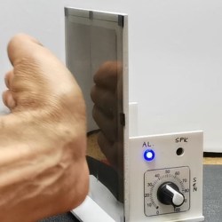
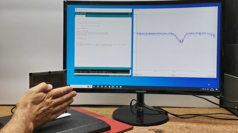
[mircemk] shows how to create a simple non-contact proximity sensor using little more than an Arduino Nano board, and a convenient software library intended to measure the value of capacitors.

The basic idea is that it’s possible to measure a capacitor’s capacitance using two microcontroller pins and the right software, so by using a few materials to create an open-style capacitor, one can monitor it for changes and detect when anything approaches enough to alter its values past a given threshold, creating a proximity sensor.
The sensor shown here is essentially two plates mounted side-by-side, attached to an Arduino Nano using the Capacitor library which uses just two pins, one digital and one analog.
As configured, [mircemk]’s sensor measures roughly thirty picofarads, and that value decreases when approached by something with a dielectric constant that is different enough from the air surrounding the sensor. The sensor ignores wood and plastic, but an approaching hand is easily detected. The sensor also detects liquid water with similar ease, either in the form of pooled liquid, or filled bottles.
We’ve also seen a spring elegantly used as a hidden touch sensor that works through an enclosure’s wall by using similar principles, so the next time you need a proximity or touch-sensitive sensor in a project, reaching for the junk box might get you where you need to go. Watch [mircemk]’s sensor in action in the video, just below the page break.


Something is not right there: Introducing another object, or increasing the dielectric constant, is expected to *increase* the capacitance, not decrease it.
The hand increases the “self capacitance” of the circuit.
Self capacitance arises from any single plate into free space. By putting your hand up close, you’re increasing the self capacitance of the circuit.
Been there, done that, it breaks down almost instantly when there’s poor ground and other electrical interference.
In such conditions, a simple wire sticking up from the Arduino’s analog pin can measure your hand from a meter away, by the amount of 50/60 Hz current leaking through. It makes for a good demo about why you shouldn’t leave your input pins floating.
So in effect a simple Theremin.
For Arduino cap touch, please check out the adc cap touch library. It literally just uses one pin, and is wayyyy more robust than all the other ways of diy cap touch sensing for Arduino
This. Lots of MCU families have capacitive touch sensing, ranging from simple buttons using one pin to sliders and wheels (think iPod wheel) using three pins. I also remember reading a good explanation of how it worked in a user manual, but I don’t remember what MCU it was; I think it had a dedicated peripheral for capacitive sensing, but the same principle works even with generic I/O pins.
One method, briefly, was to make a pin an output. Hold for a while, then flip its state, wait a very short time (microseconds), and turn it into an analog input. Measure the input voltage. Done.
More complex schemes measured both polarities and some used two pins, one acting as a guard ring, or allowing the measurement of mutual capacitance.
Did you know that RP2040 has an input multiexer for ADC that connects to the 1pF sampling capacitor?
So apparently you can switch the input at a pretty high frequency. Imagine draining the charge of the C-under-test pin while charging up the 1pF internal cap and then toggling the 1pF between the CUT and 3V3 a couple times to simulate larger capacitance, slowly shuttling a known amount of charge to the CUT. Then measure the resulting voltage at CUT.
With enough oversampling, this arrangement can measure changes of about 1/10 pF pretty reliably. It would have to be calibrated for absolute precision if desired, but it’s an interesting alternative to measuring capacitance with the traditional time-to-digital that suffers from the environment noise quite a lot.