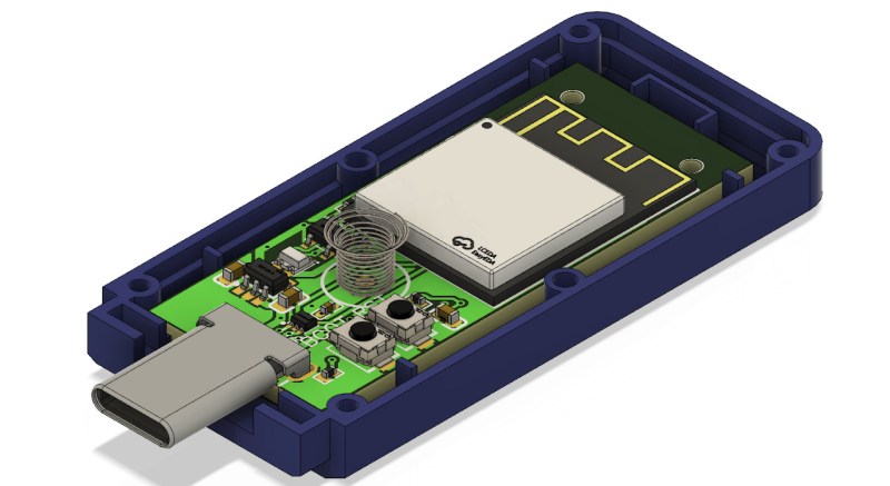
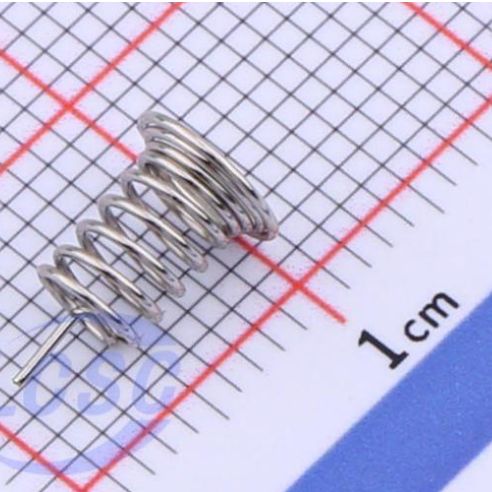
When [Daniel Eichhorn] designed the Pendrive S3 project, he wanted to use an off-the-shelf USB enclosure but also add a button for the user to start certain actions. Drilling a hole into the enclosure would be an option, but decided a touch sensor on the top of the enclosure would be much more elegant — not to mention better at keeping dirt and moisture out. To bridge the 6.3 mm spacing between the PCB and the top of the enclosure [Daniel] used a small, 7 mm PCB-mounted spring.
Although capacitive sensing works with just about anything that’s electrically conductive, it’s important to get the conductive element as close to the user’s digits as possible. Using a spring here has the advantage that when the enclosure is closed up, the lid will push down onto the spring, which will not only compress slightly, but also provide the best capacitive sensing experience when e.g. the enclosure flexes or warps over time on account of always being pressed against the inside of the lid.
While hardly world-changing, this is another neat design tip when you’re looking to turn more surfaces into touch controls. Just keep in mind that capacitive sensing is notoriously fussy and any trace and spring are also excellent antennae for stray EMI. Nobody likes random capacitive button inputs, after all.


Capacitive touch for me is one of those “magic” areas within engineering. I do understand the textbook concept of it, but the practicalities are still obscure
Like the Theremin, it feels like magic even if the principles are clear.
I spent a significant amount of time years ago trying to improve the performance of a captouch device that another engineering firm had designed, just via software (client fired them and didn’t have the money for a full redesign). Hoo boy that was painful; it was the absolute worst design choice and physical buttons would have been 100x better in all respects.
A pox on everyone who thought touch interfaces in automotive applications were a good idea. A pox!
This could be my next pit to fall into. Now that I’ve somewhat figured out oscilloscope measurements, digital signals and basic RF transmission related stuff to somewhat intuitive level. I remember long time ago how AC was was also hard to comprehend.
But there is a risk that magnets cease to be magic during the process.
I just disassembled an induction cooktop with a solid glass top that used this for all of its buttons.
I’ve seen sticky copper tape with a piece of wire connecting it to the PCB in devices. For people who don’t have such a spring available or don’t want to order/design for one for a single device…
A few times I’ve just soldered a wire to a penny and hot glued it to the underside of whatever surface I wanted the sensor on. Works and only costs me a cent!
That’s cool, but I don’t know if it’s legal in the US, though IANAL. “Treating” pennies and nickels is forbidden by US law. There is an exemption for “educational, amusement, novelty, jewelry, and similar purposes as long as the volumes treated and the nature of the treatment make it clear that such treatment is not intended as a means by which to profit solely from the value of the metal content of the coins”. I don’t know if producing a one-off sensor falls under this exemption. I also don’t know if soldering counts as “treatment”, since it’s largely reversible. Still, to stay on the safe side, I’d use a dime, even though it’s more expensive.
AFAIK if it’s for personal use and not on a large scale the gov couldn’t care less. At least I’ve never gotten a knock on the door by uncle sam for doing this lol!
The “defacing” law only applies to altering currency in an attempt to pass it off as a different denomination/value. Pennies on railroad tracks or those crank machines that stretch them and imprint a design are not illegal.
That said, there is a notable case among coin collectors. In the US during 1943, the pennies were minted in steel rather than copper to conserve the copper for the war effort. However, the Philadelphia mint had a few copper blanks in the presses at the end of 1942, and ran those through to completion before switching to steel. There is no record of how many copper pennies were produced, but only 7 or so have been confirmed as genuine. IIRC, each value at over $200k. Many counterfeits have been made by electro- or chemical-plating the 1943 steel pennies, but they can be identified by using a magnet.
Similar, I’ve seen small sponges wrapped with copper mesh glued to the pad on wearable BLE devices.
It should work better if between the spring and the enclosure is a piece of foil, to increase the capacitance.
Some of these springs have a bit of extra wire coiled “flat” at one end precisely for this reason
Could put the sensor on the underside of the board. It’s closer to the enclosure on that side.
Worked at a well known home countertop appliance company a few years ago that was in the process of phasing out captouch buttons on any of their products (so I never got to work with them directly) because they were a HUGE pain to design and validate, and customers preferred real buttons in focus group testing. But internally the PCBs all had specially designed springs exactly like the one in the image here that made contact with the plastic control panel.
I took apart a broken air fryer and the touch sensitive buttons were made exactly the same way. The controller pcb had maybe a dozen springs spaced an inch or so apart, each with an led at the base for visual feedback. I imagine that a lot of commercial products use this trick.
I have a device which is controlled by several touch button like these. It uses a SOC (Shenzen SinOne Microelectronic Co.) SC93F8433 microcontroller which incorporates Touch inputs, so with springs connected directly to mcu (through 470 Ohms resistors) nothing else.
I want to modify the way the device is working, but finding out how to rewrite and flash my own program seems too troublesome for such a rather unknown chinese mcu, and i have not found any opensource project would could provide informations about how to compile code and flash these mcus.
Using a ordinary mcu without existing touch button support would also be far from ideal, since it would require not only to replace the mcu, but also to add electronics to add touch input capabilities to mcu without it. And other comments seem to say that it is not an easy task to implement this reliably.
So it seems that i should probably use some other mcu with also dedicated touch inputs, and it seems that ESP32 could be a candidate! With the bonus to be able to monitor/control my device by Wifi, which could be useful.
Any other advice maybe?
Way back in 2010 is when I was playing with Cypress capsense chips. I started with a “PSoC FirstTouch Kit (CY3270)” based on the CY8C21434. When I saw the app note for using springs with capsense circuits like this, it blew my mind. I was having enough trouble understanding the details for getting capsense pads to work properly under various thicknesses of acrylic so the idea of putting springs in between to enable larger gaps between the PCBA and “user touch” surface just seemed crazy.