Are you the kind of hacker who tries to pick up FreeCAD, but doesn’t want to go through a tutorial and instead pokes around the interface, trying to transfer the skills from a CAD suite you’ve been using before? I’ve been there too, and in my experience, FreeCAD doesn’t treat such forays lightly. It’s a huge package that enables everything from architecture to robotics design, so if you just want a 3D-printed case for a PCB project, the hill can be steep. So let’s take that first simple project as an example, and see if it helps you learn a little bit of FreeCAD.
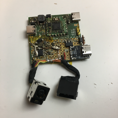
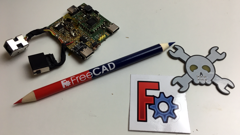
As motivation, I recently built a USB-C PSU board that uses a DC PSU and does the USB-C handshaking to provide 20 V to a laptop. It is currently my only 100 W USB-C PSU, and my 60 W PSU just died, which is why I now use this board 24/7. I have brought it on two different conferences so far, which has highlighted a problem – it’s a board with tons of exposed contacts, which means that it isn’t perfectly travel-friendly, and neither it is airport-friendly – not that I won’t try and bring it anyway. So, currently, I have to watch that nothing shorts out – given the board has 3.3 V close to 20 V at 9 A, it’s a bit of a worry.
This means I have to design some sort of case for it. I was taught SolidWorks in the half a year that I spent in a university, and honestly, I’m tired of the licensing and proprietary format stuff. When it comes to more hobbyist-accepted tools like Fusion360, I just don’t feel like exchanging one proprietary software for another. So, FreeCAD is the obvious choice – apart from OpenSCAD, which I know and love, but I don’t always want to think up fifteen variable names for every silly little feature. That, and I also want to fillet corners every now and then.
For a full-open-source workflow, today’s PCB is designed with KiCad, too. Let’s see about installing FreeCAD, and the few things you need to import a KiCad board file into FreeCAD.
Pick The Right Package And STEP Ahead
First, installation. On Windows, look for this guide. On Linux, there are a few ways to install FreeCAD – not all of them might work well for you. I’m using Ubuntu LTS, where the standard repository version is too old, and the PPA freecad-daily version was way too bleeding-edge for me. I’ve found that FreeCAD AppImages are a wonderful middle ground, and chances are, an AppImage is what you should get – it ought to work for you no matter the system. It’s a hefty executable alright, but it carries all its dependencies inside to make sure you have a smooth experience despite anything, and it’s a reasonably fresh FreeCAD snapshot.
 Open your FreeCAD image, make sure it loads well, and feel free to lurk around the provided examples – there’s plenty! All you need to import a KiCad board is to start a new FreeCAD project, and to load that board’s STEP file – you can just drag and drop it. Here’s my STEP if you just want to follow along, and, let’s see what you need if you are starting out with your own board.
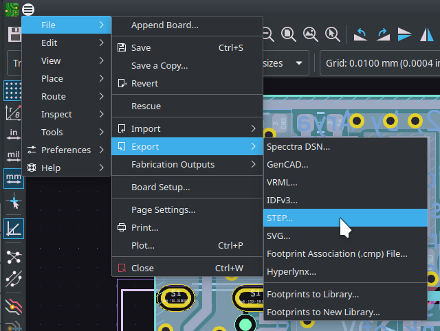
Today, we have a very simple PCB, the Altmode Friend devboard I developed as I went through writing the USB-C article series. KiCad has native STEP export – all it takes, as a rule, is going File=>Export=>STEP. Important – you want to have STEP models for all your components so that they can be exported too. KiCad libraries have both STEP and VRML models, and, VRML doesn’t work well for CAD. However, VRML models are picked by the default for KiCad components, perhaps because they’re more render-friendly. I’m not sure it’s necessary to do that anymore, but if your models don’t export together with your board, you might want to replace any .wrl model references with .step – I straight up edit the .kicad_pcb file in text editor and use a “.wrl to .step” search-replace for this. Got a .step model – now go File=>Import (Ctrl+I) in FreeCAD and load it, or, again, just drag&drop.
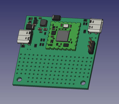
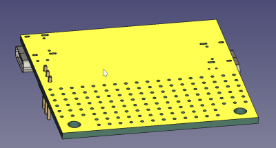
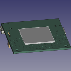
Yay, signs of life! There will not be any traces or silkscreen markings visible; you can check a KiCad-8-only option that exports them, but that will increase your file size quite a bit for barely any benefit, and the model will take a while to export&import, too. You will have a piece of green material in the exact shape of your board, PCB through-hole pads shown as holes (no plating), and the component 3D models attached on top of it, but that’s about it. Nevertheless, for mechanical design, this is more than enough.
Are any 3D models missing from your board? If the .wrl–.step conversion didn’t help, it might be that your footprint just doesn’t have a model associated, and if you can’t find a similar enough model in KiCad 3D libraries, you might need to download one. Check up with your parts’ manufacturers, for a start – places like Molex, Keystone, and many other manufacturers publish STEP files for their parts.
Alternatively, visit a place like GrabCad, make an account or bugmenot one, and treat yourself to the innumerable amount of models they have. Most of their models are either in STEP format or easily converted into STEP, and if it’s not, you might be able to convert it using FreeCAD itself. If you’ve found some part you need but it’s added to a more complex part (say, an LCD panel on an LCD breakout board 3D model) you can even use FreeCAD to yank only that part out of the multi-part STEP model, export that specific small part as a separate STEP, and load it into KiCad!
One addition you might want to know about – there’s also the KiCadStepUp plugin for FreeCAD that helps you import your KiCad boards, doing the STEP export automatically, and adding a whole bunch of improvements along the way. You can even edit the PCB outline as a FreeCad sketch, and then export it back into your KiCad PCB file with a single button! I’m not including the plugin in the article to make it as self-contained as possible, but it’s still very simple to install, and I recommend you check it out!
Interface Basics
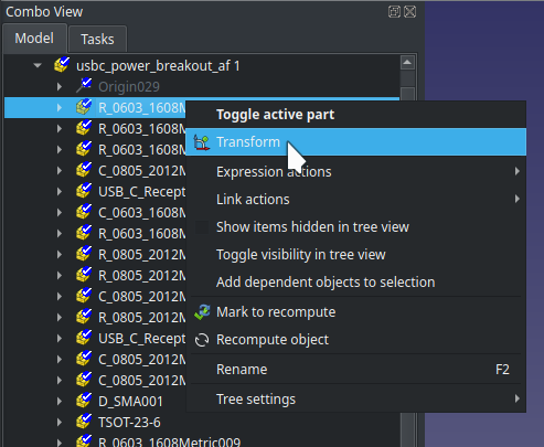 At this point, you should have a model of your PCB imported into FreeCAD. On the left side, you will have the project tree view, called the Combo View – as CADs go, this is a pretty important view. You can doubleclick the board model entry in the tree view, or right click and press
 Transform – three coloured arrows will appear and let you move or rotate the board in 3D space. Click Esc if you want to exit the model movement menu – if you’re like me, you’ll accidentally go into it every now and then, so don’t let it startle you.
Want to move around the workspace, as you will usually do while CAD’ing? FreeCAD movement bindings might not be what you’re used to, so let’s make sure you know the current ones. And, as usual, if you want to design models lightning fast and without frustration, tooltips will show the keymaps to you when you hover over toolbar elements, and, you can check the keymaps using Tools=>Customize at any point!
Want to make any model disappear? Click on its entry in the tree and press Space – it will disappear from the model view and get greyed out in the tree. Alternatively, if you want to make it transparent, you can always exit any sketches, go into the Part workbench (this is important), right click the model, pick Appearance and move the transparency slider.
On the bottom is the commandline interface and log output. If something goes wrong, that’s where it will throw a bunch of red text at you – sometimes the red text will even be easy to understand! FreeCAD doesn’t tend to use dialog boxes, so if there’s a problem, expect it to appear in red in the commandline output. There are also timestamps, which make it easy to see if the problem disappears as you make changes. (A “clear output” button would be nice.)
If you’d like to try your hand at simple operations, here’s the first task – pick Transform (doubleclick in Combo View or right click => Transform) and use the arrows to rotate the the board parallel to the XY plane (plane formed by X and Y arrows), then move the board center to approximately axis center point (X 0 Y 0 Z 0 coordinates). This is very much not required, but it can help you while you design.
Two Workbenches, Same Purpose
On the top, you will see a dropdown, that likely says Start after you’ve booted up. This is also an important one – it has workbench switching. Click on it – you will notice Part, Part Design and Sketcher workbenches. You will invariably be using the Sketcher workbench, but as for Part and Part Design workbenches, you have to pick one of these two. My suggestion is that you go with Part, that’s what I’ve learned using so far, and it works wonders for me while not having some limitations of Part Design that would be my dealbreaker. Interested to learn more? Here’s a comparison on the FreeCAD wiki.

FreeCAD is community-sourced, a lot of people contribute a lot of different parts, thanks to its modular interface. A FreeCAD workbench is one such module that people can contribute – which is how it ended up with two workbenches for the same task. There are workbenches for all sorts of stuff, including one for KiCad import and one for OpenSCAD, and quite a few more. Who knows, maybe you will feel compelled to add a workbench at some point, too! But today, let’s start with a sketch.
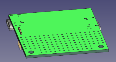
I’d start the sketch by drawing on the bottom of the PCB. Rotate the PCB so that its bottom is facing you, and click on it. That will highlight just one continuous surface on the board, the bottom surface. If you’ve accidentally selected the entire PCB as a block, all of it turning bright green, click on the background so that it gets deselected, then click once again on just the surface – that should simply select the face. Go to the workbench dropdown, select Sketcher, and press the New Sketch button. In the dialog that opens, simply press Ok or tap Enter – the default Plane face option is what you need.
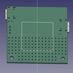
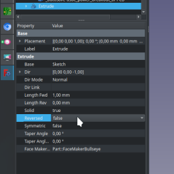
That brings you into the sketch drawing mode. Pick the rectangle tool and draw a random rectangle. Tap Esc to exit the sketch, go to Part workbench, then press the Extrude button. On the left, select extrusion length, and press “Ok”. See the extrusion? If it went into the direction you didn’t want, double click on the extrusion in model tree view, and at the bottom, look for the Reversed option; flip that.
This is the point at which I feel it’s safe to leave you alone with FreeCAD – any CAD-savvy hacker will learn the ropes from here, and if you’re looking to move away from something like Fusion360, or at least have a second option at your disposal, this is most of what you need to continue.
There’s one major thing I’ve found that’s unintuitive, that I feel like you should know about immediately. The tree view on the left panel will sometimes become as if unresponsive, and some menu items will be greyed out. If you find yourself battling that, you might have to exit the sketch you’re currently editing, or, if you have a sketch tool activated, you might have to press Esc on that to deactivate the tool. Another recommendation is – save early, save often; FreeCAD crashes like a proper CAD tool, less and less with every new version, but it is still a thing to watch out for.
Cool Features, Rough Edges, Friendly Tool
Next time, I want to show you how designing this case went, of course, and talk about things like external geometry. I’d also like to talk to you about a few things I’ve found, that you can keep in mind to ensure your FreeCAD workflow is as smooth as possible. I’ve also accumulated a list of things you want to avoid doing – we will talk about filleting, topo naming, general editing tips, and anything else that you personally think FreeCAD beginners should learn about. Make sure you leave a comment below if there’s anything you want to see discussed!


I’m curious. When you say it’s “not airport friendly,” are you saying that TSA gives you a hard time when they see it, or that it’s prone to damage during transport or use?
It’s a pet peeve of mine that TSA is trained by Hollywood on how to identify scary things. I still see examples of IADs in movies with flashing LEDs and beepers. Seriously? A terrorist is not going to go out of their way to wire up lights and sounds to draw attention to their device… only movie props do that.
I haven’t had the opportunity to bring many unboxed PCBs through a TSA checkpoint, but if I were questioned about it, I would be asking them to clearly articulate what about it they think makes it a danger to passenger, crew, or equipment, and if they can’t do so, to kindly return it to my bag so I can catch my flight.
TSA is not a LEA.
That said, if my device were especially valuable or unique, I’d probably have a padded pre-addressed envelope with stamps ready to slip it into so the apes don’t destroy it.
It’s a simpler gripe than that – I want to use it as a charger in airports while waiting for a flight, but I don’t want to get more suspicious looks than absolutely necessary =D Thankfully, I don’t have to deal with TSA, and I’m never questioned on electronics in EU (apart from that one time); in fact, I’m surprised I never get questions, given the amount and the kind of stuff I have in my carry on! As far as I’m aware, though, TSA is uniquely and outstandingly incompetent in this regard, their incompetence only matched by their self-confidence, so I you have my deepest sympathies on that one.
Obligatory https://xkcd.com/651/
It occurs to me, @arya, there doesn’t seem to be a link to or images of the finished product. How did it all work out?
The article mentions a future article continuing what was begun here.
yeah and the continuation isn’t written yet! give it a bit of time though =D
Last time i went on a flight they searched me both on the way there and back and i didnt even have anything on me
>I would be asking them…
Aaand that is the exact moment things will get difficult for you.
Chicken.
Those that don’t exercise their rights lose them.
…and those who do in airports lose their personal privacy to a pair of rubber gloves.
As always, you choose the hill to die on – whether or not it makes any difference.
I sometimes watch youtubers Mateo & lissana , in some of their videos they said Mateo (from Argentina, warm skin tone) usually gets a lot of questions in the airport about the purpose of the trip, the luggage and their drone, while Lissana( from Estonia, pale skin tone) usually get a “welcome to the country”.Something to consider if you plan to bring your DIY gadgets with you.
yeah I thought about adding a quip in my comment about this, but couldn’t work it in well; absolutely a factor!
My gripe with TSA?
Their backscatter system constantly puts a yellow alert on my junk.
I found out after seeing many sideeye/smirks between female TSA agents, so I looked over shoulder.
Not just yellow alert, but angle of dangle! L/R/C.
Yes, I’m telling everyone. Wouldn’t you?
Even in Winter?!? :)
[Arya]
I have recently bought a 3D printer and considering Freecad to make models for it.
Thanks for posting this article, although it is quite a mouthful to swallow, I will pay attention to what you have written.
Openscad clicked my brain better when we got our printer.
Among my colleagues, we have three openscad devotees, and two FreeCAD heretics, I mean, followers.
I have used OpenSCAD before and I enjoyed it, but fully functional (?) parametric design does get bothersome in certain sorts of models, sadly!
Fully Functional SW that always works is worth it. Vs shortcuts that sometimes work. I would rather work with a SW package that always does what one wants rather than one that has multiple methods of defining constants that then lead to issues when you do not know exactly when nor where the definition exists.
OpenSCAD rocks. One page cheat sheet. And a GUI that doesn’t update. A CAD package that works year after year after year. Such that you can actually get good at it. Vs one that changes every 6 Months so you have to relearn how to use it. Or one that may go away at any time.
While it rocks for individual parts it doesn’t do assemblies well. It is also helpful if you can touch type. Unlike a GUI designed for use with a Mouse.
I’ve been climbing the FreeCAD hill lately. Let me solve 90% of your problems and inevitable frustration. Get the RealThunder fork and never look back. There are at least 3 large general reasons. Bugs, functionality, and forums. RealThunder takes care of most of the bugs, adds a lot of simplifying functionality, and you find yourself in the arrogant forums a lot less often. Think of a milder yet just as helpful version of stack overflow.
Trust me on this. Get RealThunder or look for different software altogether.
In your opinion. There are plenty of bugs in the RT fork, I can trigger TNP with little effort. There are a couple things he’s added that are interesting, but certainly not essential IMO and some even encourage sloppy work. most are now in the the upcoming 1.0 release (including the TNP mitigation, which is based on the RT mitigation.) and the improvements in sketcher in the 1.0 release, many feel are great additions.
Uh watch out! The advice in this post is really bad and you **will** shoot yourself in the foot if you follow it.
If you are looking for parametric CAD using constrained 2D sketches that are then extruded/rotated into 3D (paradigm that majority of 3D CAD uses) then you must work with Part Design workbench, not Part!
Part is CSG modelling where you add/subtract primitives (a bit like OpenSCAD works). This is a very different paradigm that has a ton of limitations in what can be modeled and how that will make you tear your hair out.
Worse, bodies created using these two workbenches are not easily used together, you could shoot yourself in the foot really badly if you try use something created using the Part in Part Design (or vice versa) without understanding what is going on.
That’s why the FreeCAD’s documentation (and most its users) recommend to beginners that you work with Part Design and completely forget about the older Part workbench’s existence.
To precise – while you can work with sketches and extrusions in Part, you combine them using boolean operations. Whereas Part Design creates a single solid directly. This has major implications on how the body is represented and what can be done with it.
If you are coming from Fusion360, Onshape or some similar CAD system, you do want Part Design and not Part workbench.
See here: https://wiki.freecad.org/Part_and_PartDesign
Ahha, I assume I’m missing something, then. I have designed five pretty complicated models in FreeCAD so far, all of them with a Part workbench, all of them having gone through multiple revisions. Could you please describe what kind of problems specifically I’d be facing? FreeCAD has its issues, but as far as I can tell, only one of them looked like it was related to workbench choice – specifically, it was a model split in two pieces from the start, which I needed and PD fundamentally can’t do, afaict.
Edit: I’d also like to know where the docs recommend PD for beginners. Last I checked the comparison pages for this specifically, I did not see anything like that.
You’re correct: PD is one model/body only, which is its primary limitation. Where it does better, though, is in building somewhat complex models and then editing them: Part tends to really smash things up if you change parent objects, and there are ways to use PD that provide a lot more robustness for changes near the root of the object not totally hosing the derived form.
“Feature editing” instead of CSG, when properly applied, creates a linear transformation from some initial shape to a finished geometry. This mimics the way you actually build the part by removing material out of a billet, or by adding material like in 3D printers.
If you change something in the middle, you cannot completely fudge up the results unless you completely change the features you’re referring to in later operations (or the software decides to mess things up, see: “topological naming problem”). If things break, that usually means you’ve broken the topology to the point that the later features no longer make sense and you should redo them anyways. In essence, you’re forced to think about the model in terms of transformations from one state to the next, where nothing “magical” should happen.
CSG is a tree of boolean operations that result in a final composite object, where changing one thing may make all the other branches make no sense at all, but the model still “works”. It doesn’t really correspond to any real manufacturing method, because you cannot mash arbitrary abstract shapes floating in space together in real life.
> a model split in two pieces from the start
Splitting a “part” in half really doesn’t make any sense in a modeling point of view, but because FreeCAD confuses parts and assemblies, we have this “feature” you can abuse.
Hmm, I’m having trouble understanding the implications, could you tell me more about what this means in practice, in terms of what you’re describing? And yeah, topo naming has been a problem for me; thankfully, I’ve learned enough to avoid topo naming problems by now… I think =D
The CSG model is a bunch of geometries that have no relationship with each other – they’re just brought into the model and then the program is told that these shapes add up to a solid object.
You do not build up on existing geometry (feature editing), instead you create new geometry at every step, so a thing like a fillet is computed as a new object that is subtracted from the model. Doing it this way makes your model way more complicated when you want things like chamfers and fillets, or shells and arbitrarily shaped funnels, and when you mash things up like this you can easily create invisible voids and pockets, or split your part into multiple pieces – which isn’t supposed to be happening.
“Feature editing” extends the toolbox you have available for operations beyond adding shapes in a boolean fashion. My pet example is sheet metal bending, where you can define folds to make a C bracket, put a hole through it, and then unfold it back to a sheet, and the holes appear where they should be drilled on the flat sheet – correct for the bend radius and material thickness etc.
This is possible because the part is modeled as transformations from one state to the next, and you can go backwards and forwards in a logical order. A CSG model of the same would be building the end result C shape directly by subtracting two pieces – and the corners would be “fudged” by whatever you guess they will be after bending the sheet. You can’t go back from the final geometry to the starting point, because you essentially started at the end.
>PD is one model/body only, which is its primary limitation
That’s just confusion. A part is a part – not multiple parts. The latter is called an assembly. FreeCAD simply mashes the concepts of an assembly and a part together, which makes it confusing for everybody.
As a long time FreeCAD user, I highly recommend starting with Part workbench. Part Design actually hides what’s going on. Part WB is arguably more capable than Part Design. I regularly choose Part WB over Part Design.
There is nothing wrong with using Part WB solids in Part Design Body’s. The problem comes when you attempt to use Part WB tools on features (Pad/Pocket/etc.) of a Body.
I think the “most users recommend” that you refer to is being done by those who don’t know how to use Part WB and have never ventured outside Part Design.
And, as for Part being CSG, it is, but, it is far from limited to primitives. You can sketch and extrude solids of any shape and never use primitives. (Just as most never use the primitives available in Part Design.) I have done many complete/complex models in Part WB and never used primitives.
I do not recommend “forgetting” Part WB, that, is a very “blinders on” opinion.
I am dooing a woodworking course and wanted to dive into FreeCad to alter the design I was given for an assignment. I played with tutorials for three full days, understand what I’m doing and have to do but the process is slow (together with that FreeCad – at least the PartDesign route I took) is not suited to many processes of woodworking.
In the end I thought I needed at leas a full day to make the drawing to a point where I could use it, but it was 9:30 PM and I needed it tomorrow morning. So I switched off the PC, got out a pencil, ruler, protractor and my trusty casio fx-82 (any desk calkie would’ve done) and did the exact drawing I needed in an hour.
But weeks later I found out that I had done all my calculations based on 9mm ply and that was no longer available and 10mm was the alternative, I spent another hour recalculating everything, while one change in FreeCad Sheets would’ve solved this for me.
+1. I’ve been in FreeCAD many times and reverted to pencil and paper to get it done. But in FreeCADs defense Inventor and Fusion 360 would not have been much help either. Nor would LibreCAD or AutoCAD. Last weeks design is on Paper. The Second version is the one I’m building as I didn’t like Version 3.
If you really want to learn FreeCAD I can’t think of a better way than follow along with MangoJelly’s beginner’s playlist: https://www.youtube.com/watch?v=NXN7TOg3kj4&list=PLWuyJLVUNtc0UszswD0oD5q4VeWTrK7JC
He does a magnificent job of this.
He’s also working on a new playlist for version 0.22 (which will be released as 1.0). And yes, the topological naming problem has finally been fixed in it. You’ll still have to download the weekly builds if you want to try it out. Things are changing pretty fast now for FreeCAD.
https://www.youtube.com/playlist?list=PLWuyJLVUNtc3j4bMQQERuioEZKt_D5jAc
Also, if you’ve ever tried to figure FreeCAD out by yourself and given up (perhaps tried to map your Fusion 360 knowledge only to get frustrated), do try out MangoJelly’s stuff.
The TNP mitigation will greatly improve the user experience. Possibly to the point the user may never experience it. But, to be realistic, it is not 100% “fixed”, it is an endemic part of parametric software.
Concur in spades!
MangoJelly vids are great, and can’t wait for 1.0 to drop.
I agree, I started my FreeCAD instruction with Darrens videos, the beginner series, even though older are a great start… Learning sketcher and the spreadsheet allowed me to make the “universal” project box… Support him on Patreon…. Cheers
I recommend MangoJellySolutons FreeCAD For Beginners tutorial series on YT (https://www.youtube.com/@MangoJellySolutions).
Oops. HHack beat me to it! :D
That example board doesn’t need a case, it needs to be encapsulated in an opaque epoxy resin to hide the evidence.
I wouldn’t let that on an airplane either. It looks ready to burst into flames if it even approaches an outlet or other source of electrical power. My advice is stop using solderbraid instead of proper wire, and touch the solder for less time with your iron. There are a lot of joints there that have clearly been over heated.
if you’re so afraid of this board, I can ship it to you with express delivery; my advice, then, is to run ;-)
it’s had an exceptionally productive life for a devboard, give the poor board a break!
That wasn’t a burn on the board as much as the person on the iron.
Pot over the shame.
nah, burning flux means there’s progress
What do the giant, not shiny, boogers of solder mean?
They mean lead-free. There’s only one potentially cold solder joint I see, the big one mid-wick, and it’s neither electrically nor mechanically important – it’s simply “keeping sure the wick lays flat to the board while I solder to its ends”.
I’m looking at a PCB that goes under a keyboard. That means modelling the case first, then moving components to avoid collisions (screw mounting posts, Bluetooth battery, USB port, etc).
yeah! the KiCad plugin is pretty useful there, as you can edit the outline of your KiCad board as a FreeCAD sketch and have your changes propagate back into the board!
It’s funny that every time I get a new laptop I install FreeCAD, and then poke the tutorials hoping I don’t startle them, and then do them om my next overseas trip, and by the time I actually need CAD for a project I can no longer make head or tail of SIMPLY ASSEMBLING PARTS🤕
So back I go to Fusion360, unable to remember why I hate myself
Multi-part assemblies is where I get stuck with FreeCAD too.
Would take any tips anyone’s got on that front.
“In general, the Std Part object was designed to serve as the basic building block to create assemblies.”
“As of FreeCAD 0.19, there is no official assembly workbench included by default with the system. Assembly workbenches are difficult to program”
That’s why. A part is not an assembly, and objects hovering in space near one another in one model is not “assembling” them. What FreeCAD is doing is a confusion in terms, which is why it sucks at assemblies. What you actually need is one of the (ill maintained) assembly workbenches to define the constraints of an actual assembly.
Wait for version 1.0 for an officially supported assembly workbench.
I even signed up on RealThunder’s Patreon to get a better assembly workbench, but its tricky. I think they try to do too many things. A few geometric constraints (2D centering plus offset, plane-to-plane glue with offset, etc) done simply and well would be better than trying for 5-axis curve integration oit of the gate. Think the add and subtract of Tinkercad. Just start there.
Hey hey looky what we have here
– Biff
https://github.com/FreeCAD/FreeCAD-Bundle/releases/tag/1.0rc1
Version 1.0!
Beware obsolete FreeCAD tutorials/instructions.
The way things are done has changed/rearranged frequently.
Instructions without version # applicable notes are certainly old and worse then useless.
Also beware breaking the underlying code engine.
Some bad extrudes can only be recovered from by restarting the app and reloading an old save.
The corruption is both in the app and in saves after the python code fails (with a wrong error message). Undo doesn’t help. Save a backup version before every extrude.
True all dat
The way the board is assembled keeps me far away from reading a tutorial on complex software. Yes, I am biased.
Well, good news, there’s a reason why the STEP I’m using has mounting holes but the board on the picture does not =D
For the KiCad export, you can check the “Substitute similarly named models” checkbox in the STEP export dialog rather than manually editing the file extensions in the board file.
Thanks for the headsup about the FreeCAD AppImages – I use Linux Lite, which uses the Ubuntu repository. I will check out the link you inlcuded.