When we first spotted the article about a one-transistor amateur radio transceiver, we were sure it was a misprint. We’ve seen a lot of simple low-power receivers using a single transistor, and a fair number of one-transistor transmitters. But both in one package with only a single active component? Curiosity piqued.
It turns out that [Ciprian Popica (YO6DXE)]’s design is exactly what it says on the label, and it’s pretty cool to boot. The design is an improvement on a one-transistor transceiver called “El Pititico” and is very petite indeed. The BOM has only about fifteen parts including a 2N2222 used as a crystal-controlled oscillator for both the transmitter and the direct-conversion receiver, along with a handful of passives and a coupe of hand-wound toroidal inductors. There’s no on-board audio section, so you’ll have to provide an external amplifier to hear the signals; some might say this is cheating a bit from the “one transistor” thing, but we’ll allow it. Oh, and there’s a catch — you have to learn Morse code, since this is a CW-only transmitter.
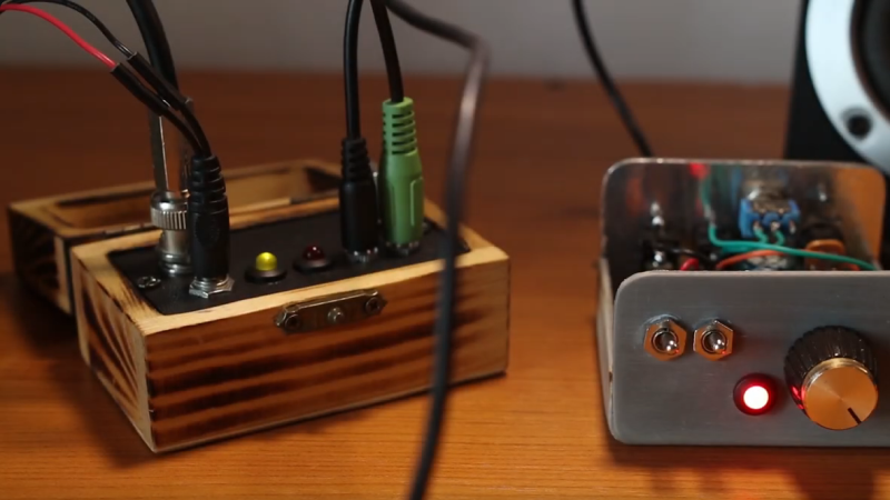
As for construction, [Ciprian] provides a nice PCB layout, but the video below seems to show a more traditional “ugly style” build, which we always appreciate. The board lives in a wooden box small enough to get lost in a pocket. The transceiver draws about 1.5 mA while receiving and puts out a fairly powerful 500 mW signal, which is fairly high in the QRP world. [Ciprian] reports having milked a full watt out of it with some modifications, but that kind of pushes the transistor into Magic Smoke territory. The signal is a bit chirpy, too, but not too bad.
We love minimalist builds like these; they always have us sizing up our junk bin and wishing we were better stocked on crystals and toroids. It might be good to actually buckle down and learn Morse too.


“Oh, and there’s a catch — you have to learn Morse code, since this is a CW-only transmitter.”
Nah, you can do a little hack and put a dynamic microphone in the oscillator line and have AM. ;)
Ideally, it’s at the transistor base and being protected by an AF transformer.
An DC receiver can hear AM without much doing and needs no modifications.
The only social issue is that some national telecommunications agencies around the globe
don’t like to see AM being used on shortwave anymore; except on 10m band.
Btw, if there wasn’t a quartz crystal stabilizing the frequency, the oscillator stage could do FM or AM+FM, too.
That’s definitely not so nice on shortwave band.
I wouldn’t worry about the elitists who pooh-pooh transmitting AM. SSB is hard, and I’m sure they wouldn’t like it if you were sending DSB, either. And for SURE they would frown on FM on HF, even though there’s nothing wrong with that. I just don’t think this would demodulate FM very well.
If you zerobeat the otjer station running AM on a DC receiver, you will hear nothing, as the opposite sidebands also cancel out, it’s one if the frustrations of DSB transceivers.
That’s not true. You will hear the modulation, but it will be a bit distorted. This is similar to what happens when you try to tune in a DSB signal with a Direct Conversion receiver. It will be distorted, but it will certainly be audible.
I’ve listened to plenty of AM transmissions using DSB and SSB demodulators. There’s some distortion caused by the fact that unless the tuned frequency is exactly correct, the upper and lower sidebands are frequency-shifted in opposite directions. But this sometimes yields a lower S/N ratio than an envelope detector.
Eh? Care to share your maths on that one? Not sure that a correct statement.
I don’t have to learn code, I will have the audio circuit in my PC decode it.
I’ve tried connecting a ham transciever to a computer and doing morse code that way. It sends very well! Any software I have seen wants you to tell it the sending speed before it can decode. How do you know that if you can’t even copy it by ear? So you guess until you manage to get at least some of the text. But then you discover that the live human sending from the other side is not a computer and so has natural variance in speed, imperfections, etc.. which the human brain is far better equipped to deal with than any software.
I think it might work though if both sides were using software and had agreed on the speed ahead of time.
You want to try AM w/ a one-transistor transceiver like this?
The signal is going to be so weak that 90% of the time even with CW you are getting nowhere. But.. that other 10%.. you hit the ionosphere just right and make a contact.
Spread that little bit of energy over the bandwidth of an AM voice signal… Good luck getting to the end of your back yard and still being above the noise floor!
Ever try the AM transmitter project in one of those XXX-in-one springy rat-shack kits as a kid? That’s basically what you are talking about.
Yes. Worth it, even to only transmit across the room. The dire warnings in the instruction booklet about “OMG unlicensed transmitter on a broadcast frequency!!!1!” only made it more exciting.
Well, the last “one transistor” radio I saw featured on HaD had one transistor all right, but several ICs as well, so this is a major improvement. I would venture a guess that with a crystal earphone you could hear strong signals without any amplification at all.
I’m just not sure why make it a crystal controlled oscillator. Several decades ago, when I first considered applying for an amateur radio license, the first-level license was called “Novice”, and restricted you to CW on crystal-controlled oscillators only, at some maximum power limit I don’t remember. I was never sure how that was supposed to work. I mean, you could send out CQ all day on your fixed frequency, and maybe some General- or Extra-class ham would answer, but what if you wanted to communicate with other Novices? I mean, it’s a bit hit-and-miss even today when it comes to finding experienced operators who are willing to slow down to under 10 WPM for the newbie.
You seriously don’t know why it is crystal controlled?? Without crystal control something this simple would almost certainly chirp beyond all recognition.
When I received my Novice ticket in 1974, the crystal control requirement had already been lifted but prior to that it was a means to better insure frequency stability for the beginner and for me the max power allowed was 75 watts input on the final amp. In the crystal control days it was normal to call CQ and then tune your receiver around to listen for any replies not on your crystal frequency. VFO’s made life so much easier but I still have my homebrew crystal controlled oscillator and still make contacts with it from time to time with 500 mw :-) 73 de wa4jat
Good history. Exactly what I did in 1960 when I was first licensed. I used a single transister with a surplus xtal hand ground to get in novice band. Interesting and very challenging.
The design is originally from Miguel – PY2OHH not my design, but crystal earphones won’t work. I think he was recommending a telephone speaker around 300 Ohm. I made a version called Pititico II that has the LM386 audio amp built in. Of course rhat one is no longer 1 transistor only. Now I am working on finishing the uu80b transceiver that does work with high impedance headphones, but it has 3 transistors. 73, YO6DXE
P.S. It was a fun project to work on.
It’s a shame I/we didn’t recognize this 10-15 years prior. Would have been a plethora of donor units on each curb.. what about actual (tube) type tvs,? Not those run off of vacuum tubes perse, but the later variety…. Surely they could have been used in some capacity
The first transceiver I ever built was the Pixie (https://vk3ye.com/projects/projpixie.htm). I built it at work out of parts I had in the junk box…it may have been a 2N3904. Crystal was the ubiquitous (at the time) color-burst crystal, so it was an 80m build. Yes, there is one IC, but it’s only to amplify the RX audio. If you had Hi-Z headphones, you could probably honestly say it was a one-transistor design.
Hi, I remember it! My father had built one from a kit, but there was a catch.
The walkman headphones had to be of higher impedance, I believe 64 Ohms and up.
However, cheap headphones also had 16 or 32 Ohms and were the much for the amp.
Speaking of the amp, the 386 in the kit was either defective or being too modern.
My father replaced it by an LM386 from the 1970s and the receiver came to life.
He later had used a Tubixie, though, which had used a battery tube. Vy73s
I forgot to mention.. Some circuits expect the correct type of headphones, so please everyone be careful.
It can happen that a circuit needs a pair of STEREO headphones, because the connection is in series (speakers in series).
Of course, there’s no stereo output; t
his trick is being used so that the impedance is being higher.
Secondly, it can help to use a transformer to match impedance.
An AF transformer (say 1:10) would be nice, but you can also to experiment with an ordinary AC transformer.
The audio signal is so narrow and low in frequency that it doesn’t matter, really.
I often use those old transformers for galvanic insulation of my shortwave radio/scanner and my PC soundcard.
It perhaps degrades the audio signal slightly, but a few KHz of bandwidth are no issue for an iron core.
The lack of humming sounds and ripple is worth it, I think.
Three cheers for Ciprian for building this. Simple is often harder to do — I found it quite difficult to get a two transistor transceiver working. But in the end it did work well. You can learn more about it, and listen to the receiver (direct — no LM386) with a micrphone taped to the headset that I used. I made 20 ham radio contacts with this thing. Here it is: https://soldersmoke.blogspot.com/search?q=ET-2
Bill HI7/N2CQR
Thanks so much Bill. It was fun indeed to work on this one and after building the uu80b transceiver, I have even more ideas to “improve” the Pititico (hi). 73, YO6DXE.
Nice circuit. Imagine next steps: Couple it with Pi Pico, maybe solar power, get VerySlow VeryLongRange telemetry.
Pi Pico uses way too much power. Try an ATTiny85 instead. This is a nice circuit but it can be done at LOT simpler.
If you really wanted to stick with a single transistor, it could probably drive high impedance headphones like you would use with a crystal radio.