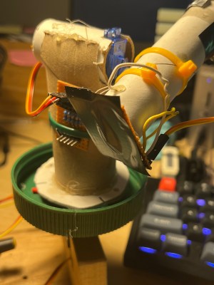
[Hugh] has been going back through episodes of the Hackaday podcast, and Elliot mentioned in episode 67 that it can often be inspiring to go back through the archives of Hackaday to find ideas for new projects. Well, he did just that and came across a single-pixel camera made using an infrared photodiode. He decided to try and hack together his own single-pixel camera, but this time on the cheap and using an ever simpler component – a photoresistor!
His description of the project tickled me – “I’ve used an ESP32, MicroPython, two servos, a peanut butter jar lid, a toilet paper roll, a paper towel roll, magnets and scrap wood for this version.” That’s certainly a much simpler bill of materials than the original (which was written up by Hackaday way back in 2015), which used a nice metal frame to hold everything together. However, there’s absolutely nothing wrong with improvising with things you happen to have to hand.

In this case, the sensor is mounted at the back of a paper towel tube, with black tape covering the front and a tiny pinhole poked in the tape to act as the aperture. Similarly to the original, the sensor is scanned over the scene in an XY altitude/azimuth pattern to capture the samples one at a time. It takes just under eight minutes to capture 8100 “pixels” in a 90×90 grid. The servos are driven using a PCA9685 PWM/Servo driver, which makes motor control a lot easier. An important lesson [Hugh] learned during construction was that weak power supplies can cause all sorts of issues when motors or servos are involved. He had been encountering uneven rotation and random halting, but as soon as a beefier power supply was attached everything worked smoothly.
[Hugh] used a much more powerful ESP32 to do the actual gathering of the analog data, which is then sent over a serial port to a Python processing engine which uses Pandas, numpy and matplotlib to do the bulk of the image processing. The resulting processed photo is very recognizable, considering the differences in linearity and sensitivity between a photoresistor and the infrared photodiode used in the original project! It really is incredible what you can do with a few spare parts, some random construction materials, and a little bit of creativity.


photo‐elektrischer bildabtaster?
Wonderful
Same concept, different wavelength:
https://josepheoff.github.io/posts/rfcamera
That uses a satellite dish and LNA to detect ambient 12GHz radiation and make pictures.
Very cool!
That’s so cool! It hadn’t occurred to me that there might be ambient 12GHz radiation…but of course there is. 🤯
You’re the same (sane?) (Smiley)【Hugh] that built this?
If so, great work!
That’s me, and thanks very kindly!
No need to put pixels in quotes – the camera is absolutely obtaining real pixels, there’s just a LOT of rolling shutter between them.
Reminds me of an old Ham radio magazine article from the early 70s. For aiming your moon bounce antenna they made a camera from a 16×16 array of CdS cells and projected an image of the moon on them. Scanned them at video speeds and sent the signal to a video monitor. The part my younger self thought was cool was scanning the slow response time CdS cells at video speeds to create a video signal.
The next step is to replace the photoresistor with a spectrometer and you have a very cheap hyperspectral camera.
Or just put some theatre lighting gels in front of it on a little spinner.
I remember an old elektor article from the 80ies detailing a scanner based on a phototransistor or diode placed on the head of a matrix printer. Software would feed paper and move the head without printing so you can scan the contents of an A4 (or us letter) paper.
Ah the things we had to do to get something from the real world into the computer in those days.
I did this in ’87: I mounted a photoresistor on the head, and read the value through the joystick (game) port. Only 160×200 or so resolution on a full page, and a few minutes per scan, but it worked fine.
I have a patent from 40 years that uses a single clear diode as a photo detector. The light source is a CRT, as used in TVs at the time. We have the CRT X/Y analog signal to know the beam location.
From this information we and scan and get a reproduction of objects.
Buck_Crowley@msn.com
Many years ago in a different life…..
We developed a tiny electro mechanical camera with a focussed image scanned by a resonating single fibre optic.
The fibre was driven in the X and Y axis by piezo electric elements. One axis just under the resonant frequency of the fibre and the other axis just over the resonant frequency. This drove the end of the fibre in a Lissajous pattern which scanned a perfect square.
A PMT tube at the otter end of the fibre literally counted photons and assembled an image into a frame store for viewing
It worked!
OMG, that’s hilarious! Very clever.
Hmm. Drive this in reverse, with a laser feeding the fiber = tiny display.
I recall something like that from around 1990, but with a linear array of ca. 128 fibers in a ribbon driven by LEDs. The ribbon had a magnet near the tip, and was driven electromagnetically.
But now with a laser you can get high brightness and bandwidth from a single fiber. It would make an extremely compact and lightweight display, and multiple lasers could make it color.
I did the same with my BBC Model B, back in the early 80’s.