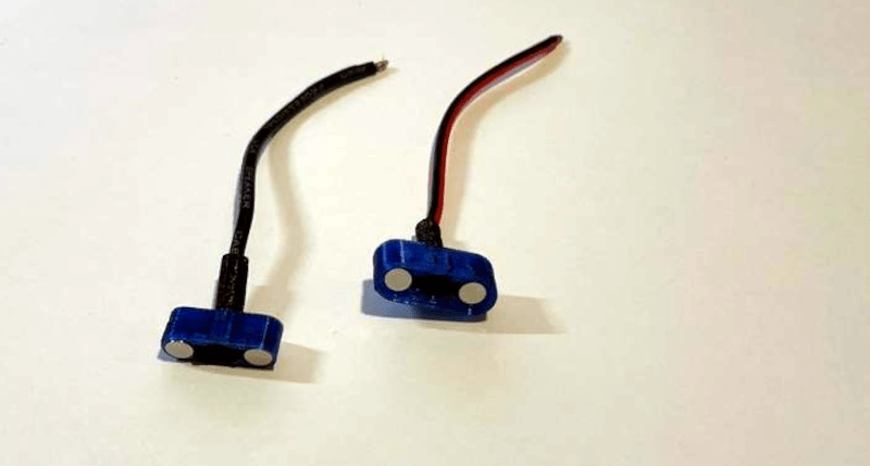
If you have a late-model laptop, you’ve probably seen how the chargers magnetically snap into place. In theory, this should be easy to recreate for your own purposes. But why reinvent the wheel when [DarthKaker] has already done the work for you — assuming you only need two conductors.
The 3D-printed shells take the usual round magnets. Obviously, the north pole on one part should point to the south pole on the other part. In addition, if polarity matters, you should also have each housing contain one north-facing and one south-facing magnet so that the connectors will only mate one way.
It appears the project uses wires soldered or spot welded to the magnets. Heating magnets sometimes has bad effects, so we might try something different. For example, you could solder the wires to thin washers affixed to the magnets with epoxy, perhaps. Or use the magnets for alignment and make a different arrangement for the contacts, although that would take a different shell design.
We have talked about magnet soldering for connectors before. Don’t forget that you can build magnets into your prints, too.


Late-model laptops use USB-C (the good ones TB4)…
Well, TB4 is limited to 100W, that’s why you’re better of charging with the USB-C on later macbooks pro, because they can get to 140W via their Magsafe 3 connector using USB-PD and there’s also less risk of launching your macbook when you trip over the charging cable.
The USB PD standard currently goes up to 240 watts, though I believe the only laptop using this is the Framework 16.
It makes more sense to me to use pogo pins for power and ground with separate magnets that just hold the connector. That is how all magnetic electrical connectors that are mass produced work. At least all the ones I’ve seen.
pogo pins
Magnetic pogo pins. Starts at 3:53 – https://youtu.be/BcUzuwP-WPI?si=QvIOc2UAlEn-K5-6&t=233
why not use small ball (sphere) as magnets. this system is better bedaus no problem with polarisation magnets. (example https://www.thingiverse.com/thing:3071684 )
The polarization problem is not with the magnets, it’s with the connector itself. If your electrical connections are symmetric along the connector, that’s fine, but if you require it to connect only one way, then ensuring that with magnets is a good idea, as the article above describes.
If your connector should be polarized this a horrible idea. It should never be possible to mechanically make a connection in the wrong direction if you have a polarized connector. Yes reversed magnet poles will keep it from being ‘permenantly’ connected, but unless you are using magnets so strong that you can’t pull the connection back apart, then all that is doing is providing a little bit of resistance to making the initial connection. And the initial connection is all you need to do to fry something that’s actually supposed to be polarized.
This problem paired with a desire to not run power through the magnets makes me think it might be worth doing something a little bit spring loaded, where the contacts are retracted a bit until the right polarity magnet is placed close enough, pulling its opposite magnet closer, then you could have your electrical contact sitting right in front of the magnet, so the magnets pulling together will bring your electrical contacts into position. still probably not ideal. And realistically, there’s got to be a simple way to do a handshake with some extra pins or something that enables the connection, because even if you are guaranteed you aren’t going to accidentally touch the wrong pins together, you can still touch the pins against some other metallic surface accidentally and short them. It would be better if the contacts weren’t active at all until you want them to turn on.
A couple of things…
I would be interested to see a “squares” breakdown on the resistive properties of various magnetic materials. An Ohm here or there could make a difference in some applications. And it would determine your current limit to keep the temperature below the Curie threshold. Ferrous materials are pretty easy, but the rare-earth and otherwise “exotic” magnetic materials may exhibit different properties.
Does electron flux through a magnetic material alter its magnetic properties? We know the “opposite” is true – electromagnetism exists with electron flux through otherwise non-magnetic or poorly magnetic materials.
These small sintered Neodymium magnets are coated to prevent corrosion, usually Ni/Cu/Ni. Resistivity of Nd₂Fe₁₄B is some orders of magnitude higher than copper, so most electron flux will take the route through the coating. Curie temperature is >310°C, the connector housing will probably melt or catch fire before the contacts fall off.
I did something similar but dropped the magnets into empty 22 long rifle brass cases they solder great.
or maybe use some pogo pins or similar and only use the magnets to locate and “lock” into the socket.
I think that was the approach in Apples MagSafe connector, which afaik was generally seen as well working.
Soldering a wire to a magnet doesn’t affect the strength of the magnet too badly as long as the magnet your soldering to is attached to another (bigger) stack of magnets.
I did this all the time in the early days of 3d printer magnetic bed probes (ie QuickDraw or Klicky)
Build in a Pogo spring connector and pad. Saves destroying magnets and is a much cleaner solution. You can then add more than 2 contacts.
I don’t like soldering directly to a Neo Magnet Coat.
This is a good idea. what needs to be added is a field concentrator that is narrower than the Neo’s OD – that acts as contact and may be soldered to. This could literally be a small flat headed bolt of some magnetic-soft metal to a little circle cut from sheet-metal with hole to attach wire to solder (it will stick to magnet always more than to its counterpart) – to something more custom/dedicated. As a plus the magnets may be recovered for later re-use as they are fitted in, not permanently modified in any way…
wouldn’t some copper foil tape over the surface of the magnets be easier ???
-G.
It makes more sense to me to have pogo pins for the electrical connection with separate magnets to hold the connector. That is how all mass produced magnetic connectors work. At least all the ones I’ve seen. It also need to have a mechanical way of preventing a reverse connection. Reverse polarity won’t cut it because you can still force it together with terrible results.
That’s the big value in having it reversible, which you can manage pretty simply with just 3 pins. 2 outside pins are connected to each other and the middle pin is the other connection.
I think ideally, you would do this and somehow ensure the pogo pins aren’t powered until the two connectors are connected, though idk how you would do that without some kind of simple handshake with the other device, or maybe you could work something out with magnets and reed switches.
If I was trying to make an improved version from scratch, I would do a magnet only on the power input side, and the receiving side would have no magnet and maybe a reed switch or something that triggers a mosfet or something to enable the connection after the cable is in contact. 3 pins for a 2 wire connection so it can be reversible, and then idk, I suppose you could do additional pins that would feed some power back into the plug of the cable to enable a connection from that end as well? I’m not an EE so this is just my rough brainstorming, but if I had to hack something together, that’s where I would start from.
If you modify the shell so that the bare wire is press fitted next to the magnet that would work.
As for all the reverse polarity whinges, just have one magnet recessed and its counterpart sticky out.
If you attempted to jam them together the wrong way (like an idiot) it still wouldn’t make contact.
Job done!