To drive a MOSFET requires more than merely a logic level output, there’s a requirement to charge the device’s gate which necessitates a suitable buffer amplifier. A variety of different approaches can be taken, from a bunch of logic buffers in parallel to a specialised MOSFET driver, but [Mr. T’s Design Graveyard] is here with a surprising alternative. As it turns out, the ever-useful 555 timer chip does the job admirably.
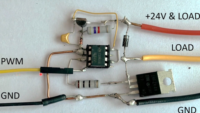
It’s a simple enough circuit, the threshold pin is pulled high so the output goes high, and the PWM drive from an Arduino is hooked up to the reset pin. A bipolar 555 can dump a surprising amount of current, so it’s perfectly happy with a MOSFET. We’re warned that the CMOS variants don’t have this current feature, and he admits that the 555 takes a bit of current itself, but if you have the need and a 555 is in your parts bin, why not!
This will of course come as little surprise to anyone who played with robots back in the day, as a 555 or particularly the 556 dual version made a pretty good and very cheap driver for small motors. If you’ve ever wondered how these classic hips work, we recently featured an in-depth look.


will this work for high-side drivers as well? it should…
I use this general configuration to pulse 2 parallel 1 ohm injectors in a TBI engine. The total current drawn is 8A peak. The 48A MOSFET is mounted on a small heatsink for reliability but it doesn’t even get warm.
The trouble here is if the Arduino crashes, the 555 output stays high. It does that when the reset pin 4 gets disconnected too, so it’s a 555 specific bug in this setup. I tried a resistor across its input to no avail.
The other fix is to avoid an Arduino crash altogether. 1k resistors on inputs, ceramic and electrolytic capacitors on the power rail, good distance between spark plug wires and Arduino wires… That’s what really worked so far for me.
Have a good day!
There are MOSFETs with logic level gates. They can be driven off a microcontroller pin with a suitable current limiting resistor when fast switching is not needed. Just watch your power dissipation and make sure you stay within the SOA.
IRLB8721 is a personal favorite of mine to keep on hand as a through-hole TO-220 jellybean part, and will switch a couple of amps directly off of a 3.3V microcontroller GPIO without a heatsink or a driver in-between. 5V MCU gets you even more current and/or can use PWM without too much worry.
Obviously in the SMT realm much better parts exist, but not quite as easy to throw together.
I love parts recommendations like this!
It’d be fun to see how the list from eight years ago stacks up today:
https://hackaday.com/2016/12/13/ask-hackaday-dude-wheres-my-mosfet/
I ordered a handful of parts from the comments here, and wasn’t disappointed by any of them.
Meh, it really is nothing special. There are a whole lot of “logic level” mosfets. Using them with a uC pin to switch a static load is valid, but when you attempt to use PWM to switch a bigger load, then it won’t work because the fet spends too much time in it’s “linear” region and it heats up too much.
When you get in trouble here, the first thing you can do is reduce the PWM frequency, as the heating is pretty much proportional to PWM frequency. Halve the times that the FET goes through it’s linear region halves the amount of energy dissipated by the FET. (Rds-on is negligible for loads of a few A).
OK, driverless MOSFETs are my new toy!
What are the requirements on the gate voltage though, I’d imagine with a 3.3V MCU, you’re not switching a P-Channel?
Logic level MOSFETS are generally laggier and more expensive than their non-logic level counterparts. If your design can allow for these compromises though, it will surely simplify your life!
Finally! A use for a 555.
It would be cool to see an circuit with 555, 741 and 386 one day. :)
Really? Diving a MOSFET that size should be rather trivial even with a micro. I don’t buy it.
For the mosfet used in the circuit, 3.3V is not enough to drive it fully open. A better choice would be a IRLZ44N. But the video is more about the concept of using a 555 in an unexpected way I guess.
And even if the MOSFET could be driven fully with 3.3 volt a run-of-the-mill microcontroller can’t supply enough current to switch it fast enough for many applications like a SMPS.
In my opinion, not a good circuit design practice to choose the wrong MOSFET for the application and then try to fix it with a 555.
The 500KHz quoted is the max frequency you could achieve if you spent all your time with the mosfet in the partial-resistance mode between properly on and properly off? As in, 500KHz if you start turning on, then immediately start turning off once it is on… This would mean, for decent efficiency and to avoid heating your mosfet too much, you’d actually have to be switching at a much lower frequency? Even lower still if you wanted to have the time the mosfet is on for scaled according to 8 or 16 bit PWM whilst still avoiding spending most time in partial-resistance mode when at the lowest duty cycle?
Good thing I didn’t mention my 556-based isolated charge pump…
I built a fuel injector tester that uses a pair of 555s to drive a MOSFET.
https://hackaweek.com/hacks/building-an-electronic-fuel-injector-tester/
I built a 555 based boost converter with feedback one sunday. Twas a slow day, I needed something to keep a lead acid battery topped up
NE555 is indeed a quite decent MOSfet driver. It boosts both output voltage and current. It’s 200mA (guaranteed datasheet value) is not as much as “real” MOSfet drivers (sometimes 3A or more), but it’s much better then a uC I/O pin, and often it’s already plenty. The CMOS version (TLC555) has a much weaker output drive ( 100mA sink, 10mA source)
https://www.ti.com/lit/ds/symlink/tlc555.pdf
One thing I dislike are part where he shows the scope. I already have an Siglent SDS1104X-E and sometimes I still think about buying an Hantek 6022BE just for fun and to play with OpenHantek. It is not a great scope, but quality is quite reasonable when you consider it’s EUR50 price point. When you work with hardware like this you have to be aware of it’s limitation. Measuring risetime of a signal, when it is just one oscilloscope sample, the only sensible conclusion is that your risetime is faster then you scope can measure. Zooming in and fiddling with scope cursors is senseless in such a case. @04:30 “Ok, that’s not so nice anymore”… Euhm, 6022 is supposed to be able to sample at 48Msps, and this video guy is sampling at 12Msps.
He mentions that the FET is getting a bit warm when PWM’med @500kHz. By lack of a better scope measuring the FET temperature rise is a simple and effective way to judge whether FET drive is good enough and you only need a finger. If you get blisters, it’s too hot. If you have a scope, then you want to see that the drive current is at least high enough to remove the “Miller plateau” from the gate signal. Maybe I missed it, but I have not seen any mention of the current through the FET. (He does say he used a “50 Watt resistor”). But does this translate toe 2A from a 24V power supply?
Its equally good at driving power bjts as well.
One thing not mentioned so far in the comments I’ve read is the necessity for a driver to sink current as well as it sources it. Relatedly, the author of the video mentions the necessity of having enough drive to CHARGE the gate, but says nothing about DIScharging it. Not all drivers are symmetrical in that sense – looking at the 555 internal schematic indicates that it IS good in this regard.
A driver may charge the gate fully at high speed – but if it fails to discharge it fast enough, overheating and possibly device failure may result.
NE555 is symmetrical. It’s output can sink and source 200mA. Just read the spec in the datasheet.
CMOS versions are not symmetrical TLC555 can sink 100mA but source only 10mA.
i did not enjoy this write up. maybe the youtube (ugh video) has actual details but the write up makes it sound like MOSFETs have an unusual current demand and the 555 is useful for its high current capability. in my experience, MOSFETs are slightly inconvenient because of their voltage demand, while their current demand is just charging/discharging a tiny capacitor, which can easily be accomplished with a tiny ‘signal’ bipolar transistor. the article basically misses the core struggle of using FETs: it all depends on your usage. how fast do you need to transition the gate in order to avoid heating it up during transition? how frequently do you need to transition the gate to achieve the regulation you’re after? what size FET do you have to use — how tiny will its gate capacitor be?
and that actual struggle is only obfuscated by this write up. i guess i’m upset about it because reading the article, it doesn’t seem vague. you wouldn’t necessarily guess it had not taught you anything about driving FETs.
You’re not wrong, but I think the main point was that if you needed a convenient push-pull driver, the 555 sitting on that anti-static foam you’ve kept since 1989 will do the job… :)
I would like to preface this by saying I’ve been in electronics well over 50 years and I was around when the 555 came out. The first ones had issues and I thought it should have been named the 666 for the spawn of the devil. 50 years is a long time to hold a grudge, so I thought about using one as a voltage sensitive driver. Nothing that had to be too accurate and in initial tests it seemed to work. I progressed to a full working model and proceeded to test it. 15ma was more than enough to run it and used a resistor and zener as a supply. As voltage increased on the reset pin, the chip would draw current upwards of 33ma @10V with no load. before the output pin would turn on and then the current would drop. Tried this with multiple chips with same result. I gave it a try, but the 555 is still junk to be avoided
Nice circuit and explanation!
You write that Threshold is connected to supply voltage in order to make the output high by default.
But wouldn’t Threshold higher than 2/3 of the supply voltage make the output go low?
This might not be relevant, because Trigger is connected to GND, which would make the output go high, but is it guaranteed that the low Trigger signal has priority over the high Threshold signal?
Might there be another reason why one should not connect Threshold to GND too?