You only really need two data wires to transfer a ton of data. Standards like UART, USB2, I2C, SPI, PS/2, CAN, RS232, SWD (an interface to program MCUs), RS485, DMX, and many others, all are a testament to that. In particular, I2C is such a powerful standard, it’s nigh omnipresent – if you were to somehow develop an allergy to I2C, you would die.
Chances are, whatever device you’re using right now, there’s multiple I2C buses actively involved in you reading this article. Your phone’s touchscreen is likely to use I2C, so is your laptop touchpad, most display standards use I2C, and power management chips are connected over I2C more often than not, so you’re covered even if you’re reading this on a Raspberry Pi! Basically everything “smart” has an I2C port, and if it doesn’t, you can likely imitate it with just two GPIOs.
If you’re building a cool board with a MCU, you should likely plan for having an I2C interface exposed. With it, you can add an LCD screen with a respectable resolution or a LED matrix, or a GPS module, a full-sized keyboard or a touchpad, a gesture sensor, or a 9 degree of freedom IMU – Inertial Measurement Unit, like a accelerometer+compass+gyroscope combination. A small I2C chip can help you get more GPIOs for your MCU or CPU, or a multi-channel motor driver, or a thermal camera, or a heap of flash memory; if you’re adding some sort of cool chip onto your board, it likely has an I2C interface to let you fine-tune its fancy bits.
As usual, you might have heard of I2C, and we sure keep talking about it on Hackaday! There’s a good few long-form articles about it too, both general summaries and cool tech highlights; this article is here to fill into some gaps and make implicit knowledge explicit, making sure you’re not missing out on everything that I2C offers and requires you to know!
Basics And Addressing
Instead, if your device is the kind you expect to return important data at random points, there’s often an INT pin – the INT pin is not included in the standard and usually is not required to use any I2C device, but if your IC or breakout exposes the INT pin, you should consider using it, since it will save you a fair bit of CPU time spent polling your device for data.
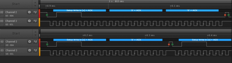
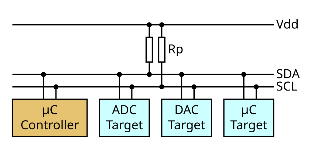
I2C is wonderful in that you can put a large number of devices on your bus – as long as your communications can physically stay stable. How does it work? Addresses. Devices are pre-programmed with an address you can use to talk to them, and you can query a bus to get a list of addresses that the connected devices respond on. Some devices can only have a single address so you can only add one of them to a – unless you hack it in one of the ways I’ll describe below. Many devices that – for instance, SSD1306 displays have a single pin you can tie high or low, so you can put two of these devices on the same bus, and GPIO expanders tend to have three pins that result in eight possible addresses. Rarely, there are devices that let you reprogram their address with a command, too.
An I2C device’s address is specified in the datasheet. Beware – addresses are 7-bit, and during transfer, the address is shifted and the least significant bit signifies whether a write or read operation is happening; some datasheets will show the address in its proper 7-bit form and some show it already shifted. The way you can notice the latter if you see separate read and write addresses specified – that’s a non-shifted address. A surefire way is to connect your device to any I2C controller and scan for devices, of course. I2C addresses aren’t unique like MAC addresses, so, there’s way more kinds of I2C devices than there are addresses. Here’s a database you can check for fun, but it’s definitely incomplete. 10-bit addresses exist and they do widen the address space comfortably, but they’re still not that popular. Remember – an I2C bus can be scanned, and it’s a pretty wonderful feature – it gives you a sanity check showing that a device is connected, a check that you don’t really get with interfaces like SPI and UART!
Clocks And Pullups
There’s three standard I2C clock speeds – 100kHz, 400kHz and 1MHz, some hosts and devices can go even higher but it’s not especially prominent. Technically, you can go higher or lower, software I2C implementations often do, but some devices might not like it. Hosts often run at 100kHz, but it’s common that you can up the frequency and switch it into 400kHz; however, there’s hosts that are hardwired to 100kHz operation, like VGA/DVI/HDMI port and desktop/laptop-internal I2C controllers.
This affects, and sometimes, if you have choice between I2C and some other interface, speed might be a deciding factor. For example, take SSD1306 or SH1106 OLED screens – they can be connected through either I2C or SPI, so if you’re using a breakout, it just depends on the way it’s wired. You won’t be able to send data to an I2C screen as quickly over SPI, because of the inherent data cap – they supports SPI links at multiple MHz clock rate, whereas an I2C link will be limited to 400KHz. Want faster screen refresh? You’ll want to wire the screen into SPI mode. Fine with possibly lower FPS? I2C is a valid choice, then.
You need pullups – and you cannot use GPIO-internal pullups like you can do with buttons, they are too high of a value as a rule. A typical range for a pullup is from 1K to 10K – going too high will distort the signal on the bus, and going too low will make the bus impossible to drive. Raspberry Pi boards use 1.8K pullups on the dedicated I2C bus, 4.7K is another popular value, and I’ve had 10K pullups result in unstable communications at higher speeds, so I typically go lower a fair bit, using 1.8K, 4.7K or 5.1K pullups. Mind you, if both your device, so if an I2C sensor breakout is failing to respond when connected to a Raspberry Pi but it really should work, check whether you maybe should desolder or disconnect the pullups on the sensor board itself.
I2C is pretty cool indeed – all those devices I mentioned in the intro, they’re a breakout board and a cable away, often, you don’t even have to solder. Looking to use I2C on your board as an expansion interface, but don’t know what kind of connector to use? It’s pretty simple, I’ve talked about it in my article on I2C ecosystems. One five-pin header and one four-pin JST-SH is all you need, and you can even get vertical JST-SH connectors if space is a concern!
Next time, let’s talk more about I2C devices, the kinds of I2C interfaces you will encounter and all the places they are usually hidden in, types of I2C transfers you can do, and notable implementation nuances, – leaving no stone unturned as usual.


Advanced i2c might be more interesting, pitfalls/timeouts/errata/clock stretching.
interesting hacks, too. Things which are not technically ‘i2c’ anymore (as in ‘not complaint with the standard’), like high speed mode using push-pull ouputs or other ‘hacks’ to the pullups. Active pullup circuits can speed things up, or maybe current-source pullup instead of a simple resistor. Or using a spare GPIO to ‘blip’ the line high to help overcome the parasitic capacitance and speed up transmission…. there are lots of interesting hacks possible to use i2c in ways it wasn’t originally envisioned.
Hardware risetime accelerators exist!
What I’d like to see is chips that can use multimaster to wake up the mcu via i2c.
Static Buffer Offsets, and chips that will deal with them too…This was a real PITA for a long distance high noise, but necessarily 2 seperate isolated busses I was working on! The PCA9616 produces a rather large offset, and most isolaters allow for a very low offset! My eventual solution was to use a PCA9544 – a multiplexer I was already using elsewhere in my project, because its Vil/Vih were the full range .3VDD/.7VDD, its offsets were quite low, and since the isolated busses being connected to might be switched off, the multiplexer isolated that condition from the rest of the bus. I also found a TI isolater would work to bring the offset back to 0 “backwards” (the high capacitance tolerant side towards the PCA9616 and then 2 more isolaters with their low capacitance side facing the first). This was an expensive solution, and as I mentioned, it didn’t survive powering down one side as should have been obvious from the start given the pullups would be unpowered….but I had thought in error that the isolaters were “smart” enough to recognize the other side missing power, despite nothing in the datasheet saying so (Yes, that was quite stupid on my part). I learned a bunch, but found there wasn’t much help online with the problem. You’re just supposed to already know what Vil/Vol and Voh/Vih mean, and you’re just supposed to pour over datasheets, buy tons of parts until you find a solution that works. The only glimmer of hope was NXP’s 0 offset buffers….which are discontinued. They also made a 0 offset multiplexer, which is still in production, but it is not, in fact, 0 offset. So despite the old press releases saying so, the datasheet disagrees. I tested to find out and yes, the datasheet is correct (not shocking at all, but I had hoped).
I’m still fairly certain the knowledge is out there, but maybe google with its ludicrous temporal filter that favors new things and that cannot be disabled is burying the results, as it often does….Its also not documented that its doing it, but search for a scientific paper you know exists. You’ll only be able to find recent tangentially related, but not at all what you’re looking for results. The paper which you know exists will porbably be on page 900 or so. If you knew the exact phrase of the title and put it in quotes, you might be able to find it on page 20 – after all the papers citing it were displayed, but I’ve digressed into a rant…The real point is I’d like to see a recent (and so findable for the next few months or so) writeup on tools to deal with complicated buffered busses and how to deal with branching, powered off segments with the static offsets induced. :) I sure hope the isolater method isn’t the best known method…
Always great to see Saleae on the cover.
Not really.
They have priced theirselves out of most of the market. They were expensive to begin with, and instead of selling their entry model for some reasonable price (I would have paid EUR50 for it back then, and without the fancy silly aluminum box), they just stopped selling it, and then over a few years tripled the prices of the rest of their products. For most hackers the Chinese clones for EUR10 or less are a much better deal. I would much rather see a Sigrok / Pulseview screenshot. That project really deserves some more love then it gets. It has plenty of capabilities to debug all kind of microcontroller projects, From I2C, SPI and Uart to a whole lot of other protocols. Pulseview has 100+ protocol decoders, and you can write your own too.
With a sad heart I admit I bought a Kingst LA2016 (Cost EUR120) when I needed more channels and more bandwith then the EUR 10 dongle can deliver. I would much rather have bought a similar LA but which directly supports the Sigrok / Pulseview project.
“You need pullups – and you cannot use GPIO-internal pullups like you can do with buttons, they are too high of a value as a rule. ”
If the bus only has a single master (which is the most common case) and it’s not a dedicated peripheral you can mostly get away with internal pullups by just driving SCL/SDA directly when you know it’s supposed to be driven and waiting when it’s not.
But that’s a total hack and you should always just use pullups.
“One five-pin header and one four-pin JST-SH is all you need, and you can even get vertical JST-SH connectors if space is a concern!”
“Looking to use I2C on your board as an expansion interface, but don’t know what kind of connector to use? It’s pretty simple, I’ve talked about it in my article on I2C ecosystems. One five-pin header and one four-pin JST-SH is all you need, and you can even get vertical JST-SH connectors if space is a concern!”
I know tons of boards/etc. just use I2C as a method for random connections, but it’s worth thinking about logic levels, unpowered connections, and bus capacitance if you end up wanting to do that, and if you drop a buffer before it, clearly define what the I2C buffer is in any documentation note where the pullups are, etc. There are I2C buffers that can’t be connected together, for instance.
There are devices out there that are stupid sensitive to live voltage on unpowered inputs, so if you don’t spec where pullups are/etc. you can get cases where everyone puts pullups everywhere and you have an unpowered device connected to a powered device and Bad Things can happen. Plus, of course, if everyone keeps adding pullups, the bus can go kaput quickly.
Side note about pullups: while a stronger pullup (lower R) can improve communication on longer/faster I2C busses, they have an clear impact on the power consumption. A common trick on battery-powered boards where each mA counts is to switch them on/off with a MOSFET to spare energy. At the price on an extra IO pin.
“A common trick on battery-powered boards where each mA counts is to switch them on/off with a MOSFET to spare energy.”
To be clear, it affects the dynamic power consumption, not the static, so it’s trickier than just “switch on when you’re trying to talk to something” – that won’t save anything. You need to be actively turning it on and off during a transaction, which makes it harder to run fast anyway.
There are buffers with integrated rise-time accelerators that can automatically do it, but you need to be careful on those because they can oscillate.
If you know the device you are talking to doesn’t clock stretch you can omit the pullup on SCL and just drive it with a push-pull driver instead of open-drain. You can do the same with SDA while writing data.
That only leaves dynamic consumption while the device is sending zeros back. To minimize this you want the pull-up resistor to be as high as possible and only enabled during device transmission. A high value of the resistor will lengthen the rise time, reducing the clock rate and thus increasing wasted power. You can calculate/determine the optimal resistor for your specific board.
If you need to reduce the current even further, only enable a (smaller) resistor a small fraction of the time after SCL transistion. If your MCU has a comparator you can use it to lower the threshold on SDA, but make sure turning on the comparator does not use more power than what you are saving.
You don’t even need the FET: you can use a second I/O from the MCU, and if you want to be really sleazy, just put a small series resistor inline with the SDA output, and drive it high right after the clock, then float it.
It’s also worth noting that if you’re really trying to conserve power with I2C, risetime accelerators (however it’s done) can also help if the MCU’s input are Schmitt triggers, because a slow risetime can cause dramatic power increases in that case.
About pullups: The specifications – well, specify a minimum current that a slave/target/whatever must be able to sink. A device may be able to sink more current, always check the datasheets!
Also last time (long ago) i checked the specs http://www.nxp.com/documents/user_manual/UM10204.pdf (a link would have been nice) were quite readable. It is worth a look, for once that specifications are freely available…
True however different frequencies have different requierments. For 100 and 400 KHz 3mA is the max required but at 1MHz I think it’s like 50mA or something. At higher speeds you need to be able to sink more current because the pull ups need to be smaller so you can flip signals faster.
Yes, indeed. By the time i looked at the specs the 1MHz mode did not exist.
How practical is it to use 100 khz i2c for cheap comms over longer distances, like 30 m?
With no buffer at all, there’s no chance. There are several long-distance I2C buffers available (PCA9615, P82B96, PCA9600) that would be able to do 100 kHz over 30 m, although that’d be pushing it a bit (the various app notes typically say 100 kHz @ 50 m), and it’s important to note that it’s no longer a 2 wire bus in those cases, but at least 4: they’re more properly “bus converters” rather than “buffers.”
There is an active terminator IC, LTC4311 which can allow a bus to be extended to about this distance at up to 400 KHz.
Adafruit have a breakout for about $10.
You are going to have a very bad day. Don’t try this. With special IC it can work, but even then it probably won’t be reliable. I tried something similar…
Using 10BASE-T1L would be a better option, 10 mbit over a single twisted pair.
Using an IP network would certainly be much more overhead, but you benefit from the ECC, checksums, and retransmission mechanisms built into TCP.
As everyone else said, you’re going to have a bad day when you try this. I2C over 1M cable has already caused me enough problems to get gray hairs.
But, I’ve used RS422 over 120M of ethernet cable with zero issues, if you don’t want the complexity of ethernet but still want long distance.
echoing I2C over 1 meter cable was a terrible experience, use something differential or some other range extender.
I’d like the next episode to go into some detail about I2C distances and capacitance issues. Looking forwards to reading the comments already !!
The problem, as with a ton of things I2C, is that there will automatically be 2 camps: one camp that follows the specs directly and says it’s complicated and you need to be careful, and a second camp that’s “oh I tried it out and it worked fine.”
I2C is really, really forgiving in a lot of cases, but the problem is that it’s a synchronous protocol with electrical specs as well. Which means you need to make sure both the signaling and timing are met. Some devices don’t care about the timing, whereas others will.
Ahem, “DMX” (DMX512?) uses RS485, SPI needs more than two wires… Just saying…
Well, if you start out with four, you don’t always need chipselect, so then you have three. And I have seen devices that ignore miso, so there’s your minimal two. The clock and the mosi pin!
single-direction SPI only really needs two wires – you can drive a SSD1306 or SH1106 display like that, for instance! The data transfer is unidirectional, so there’s only one data wire, and CS is very often optional.
“– if you were to somehow develop an allergy to I2C, you would die.”
(Snort! ) (LOL!)
There are a number of grammatical errors in this article, most often in the vicinity of hyphens, as if a number of copy-paste operations were performed in a hurry. Not that I’ve ever done that. 🙃
Nevertheless, it’s still fairly easy to understand what was meant, and well-written outside of those errors. I2C is amazing IME, and solves many communication issues with fewer wires. But as mentioned, one can definitely get into trouble with long runs between components, and high-EMI environments, where even stronger pull-ups won’t save you.
It also seems a few hyperlinks are missing
Really, it would be nice if someone went back and corrected the grammatical errors. It makes it rather difficult to understand several key sentences.
And then there’s I3C…
not dead yet?
Does anyone know of a standard (I2C or any other) that can do auto-discovery AND auto-enumeration?
I’m looking for something to chain several modules together and don’t want the user to have to fiddle with setting addresses and I need to be able to determine on which “position” on the bus/chain the module is sitting. For my use case data rates are low (like 1-10 kBaud range) and distances are short (< 30 cm).
Dallas 1-Wire or something inspired by this?
The floppy bus. Which used a piece of ribbon cable that was physically flipped around between the first and second slave (which you could still say at the time floppy was around) connector
Your question reminded me of reading this very cunning i2c hack which my brain filed away incase I ever found a use for it.
https://hackaday.com/2018/05/23/automatic-i2c-address-allocation-for-daisy-chained-sensors/
Thanks everyone! ^^
Wait… 9DoF?
1. Up/down
2. Left/right
3. Forward/backward
4. Pitch
5. Yaw
6. Roll
What are the other 3?
I can imagine deformation s maybe?:
7. Up/down stretch/squish
8. Left/right stretch/squish
9. Up/down stretch/squish
But those aren’t “movement” controls.
At that point you could have all sorts of deformations.
6 more dof for twisting each face.
12 more for shearing each face.
So many others. But none are movement.
Correction:
9. Forward/backward stretch/squish
“degrees-of-freedom” in the purely mathematical sense, not the physical sense.
The 3-axis magnometer is treated as an additional 3 DoF, as opposed to being integrated into one of the 6 physical ones, since a magnometer provides a 3d orientation vector that isn’t really redundant to a linear accelerometer or a rotational accelerometer (which is a more accurate description than “gyroscope” to my mind)
A barometer/altimeter is commonly considered a 10th DoF for IMU purposes as well.
The math is the subject of entire textbooks, but the general idea is that a linear accelerometer and a magnometer are basically sufficient for determining pitch, roll, and yaw of an object of fixed position and varying orientation. Adding the rotational accelerometer (for the most part) allows you to free up the linear component by helping remove the gravity vector, which the barometer also helps with.
Okay…
But an IMU is an Inertial Measurement Unit.
It is measuring acceleration to estimate movement.
If I put a thermometer and a barometer together, I don’t get a 2dof thermometer.
This is likely yet another case of people using a word wrong because it is easier, and causing confusion.
The inevitable response to my commentary is “but people understand it anyway, so it’s not a problem.”
Wel, clearly not “everyone” understands…
9DoF means 9 sensors, 3 sensors of 3 different types.
a 3-axis accelerometer measures acceleration in 3 axis, you can use this to estimate x/y tilt angles (not heading) in non-zero-g environments and you can integrate it to estimate position if orientation doesn’t change.
a 3-asis gyro measures rotation speed around 3 axis, integrating it estimates orientation
a 3-axis magnetometer measures the magnetic vector (usually earths magnetic field), if you know orientation of the magnetic field you can determine heading, but only 1 tilt angle
combine the 3 and you can estimate position, orientation and speed with various limitations and assumptions.
Integration causes drift and needs a starting value.
A magnetic sensor requires calibration and orientation of the magnetic field depends on the lattitude. At magnetic poles you cannot determine heading.
In a zero-g environment (or free-fall) you lose the orientation data of the accelerometer.
As another user mentioned you can combine it with a barometer to estimate altitude. You can differentiate this to determine vertical acceleration.
You can also combine it with GPS.
I even read about using a light sensor and a low-drift real-time clock to estimate latitude and longitude using sunlight.
Often a Kalman filter is used to combine data of different sensors.
There’s a good I²C page on Wikipedia.[1] NXP provides the Official I²C Specification Rev.-6 as a free download via archive.org.[2] There’s even an I3C bus now.[3] In 2021 I²C went “Woke” and changed the terms “master/slave” to “controller/target” to align with the I3C bus specification, and generally cause needless confusion.[4]
References:
I²C – Wikipedia
https://en.wikipedia.org/wiki/I%C2%B2C
Official I2C Specification Rev 6 (free) – NXP
https://web.archive.org/web/20210813122132/https://www.nxp.com/docs/en/user-guide/UM10204.pdf
I3C (bus) – Wikipedia
https://en.wikipedia.org/wiki/I3C_(bus)
I²C Revisions – Wikipedia
https://en.wikipedia.org/wiki/I%C2%B2C#Revisions
I never understood the problem with master/slave terminology. We are talking about one chip commanding another chip and that chip has to follow the commands. Master/servant is a good alternative if you want to avoid the term slave since it starts with the same letter and preserves the roles. But not needed in my opinion.
“controller/target” is subjective as a “motor controller” can be an I²C “slave” and therefore a “target.”
A more objective term would be clocker/clocked as the master controls the clock.
Anyway instead of replacing terminology we now have inconsistent terminology. The article doesn’t even mention the term slave anymore. Beginners will be confused as a lot of datasheets, tutorials and device drivers still use the non-woke terminology.
I will keep using the term master/slave for I2C and SPI devices and keep using the term master for the default git branch. I don’t want to work with people who make a problem out of it. Keep politics out of my electronics and go cry in a corner!
Simply put, I consider the old terms cringe; as for beginners being confused, you’re very much underestimating beginners.
Calling it “cringe” is probably too simply put. Calling them dominant and submissive would be cringe, assuming there’s no preexisting context in which that doesn’t refer to a work-inappropriate topic. But master/slave doesn’t seem to be the same sort of situation.
It’d have been very easy to say “Hey, there’s no need to say slave instead of servant or subordinate or even apprentice/student since a master instructs his/her students”. That would acknowledge that more people who see the terms are likely to think of the abhorrent practice than the number of people who will misunderstand if we substitute another word.
But instead a surprisingly common position in opposition to the older terms is summarized as “If you use anything similar to either word in any fashion you’re intentionally normalizing human slavery and you must support the practice you horrible racist” which is a bit like getting mad at someone for something they did in your dream. I guess we can’t let masterpieces be digitally remastered from the master copies by mastering engineers who have mastered their trade, either. In the context of an original or a root version like Git, it’s a stretch too far to say it’s a reference to slavery, and to try and stamp all over all the present and former innocent uses of the word master because of it.
Way to pretend like people are objecting to the word “master”, and not the word “slave”.
My beef with I2C:
1) no timeouts
2) bus can lock
3) no errors-detection
4) bad peripheral drivers
The first 2 can be fixed.
You can manually add a timeout and find a way to gracefully close the I2C peripheral in case of timeout.
This can be hard as some I2C drivers do not have a functioning de-init function. Closing I2C can also cause the bus to lock.
Bus can be locked if a slave is in the middle of a transaction during a reset or in case of arbitration lost due to a glitch.
You can unlock a bus by trying to send a stop-without-a-start, If this fails try sending dummy clock pulses until you can (takes at most 9 pulses if I’m not off by 1).
I recommend always sending a stop-without-a-start in the init function to close all active transactions.
Since I2C is open drain a glitch can happen. And if the wrong pull-up values are chosen the voltage levels might not meet the required thresholds.
Most slaves and masters do not check against arbitration during data phase during sending. And since there is no error-detection in the standard this means there is no way to be sure if a transaction succeeded.
A robust device driver would read a register back after writing to make sure the transaction succeeded.
Some chips have an optional CRC or checksum as the last byte and I always recommend using those.
Last but not least the terrible peripheral drivers. As mentioned they often do not implement de-init functions correctly. If they have timeouts they often do not work.
Reading data often requires knowing the number of bytes beforehand. Lacking features such as reading data after a NACK (many peripheral automatically send a stop after a NACK).
And they rarely implement stop-without-a-start.
I appreciate all you hackaday writers, but Arya you really take the cake for me . I really Really love all your articles thank you you are my favorite hackaday writer by far since Brian stopped writing
Please take the time to spell, grammar, and fact check before posting.
It’s become such a big problem that some articles are not useful.
Even when that isn’t the case, you probably want to make sure you aren’t making the opposite of a statement when giving out information to people in a beginner article.
“You won’t be able to send data to an I2C screen as quickly over SPI.”
This statement literally means I2C is faster than SPI.
The next statement contradicts it.
The CORRECT statement should be:
“You won’t be able to send data to an I2C screen as quickly as over SPI.”
This is why proofreaders and editors exist.
There are so many errors on HaD that I don’t even bother to comment on them all anymore, because I would be spending more time writing corrections than reading articles. And I’m not the one being paid to write your articles.
You never mentioned IEBus. Otherwise called GA-Net or AVC-LAN by automakers, it its common in car audio.