Switch-mode technology has made inverters which take a low DC voltage and turn it into a usable mains voltage within the reach of everybody. But still, there might be moments when a mains supply is needed and you’re not lucky enough to have AliExpress at your fingertips, and for that, here’s [Rulof] with a mains inverter that is simultaneously awful and awesome. He’s made a rotary converter, from trash and off the shelf parts.
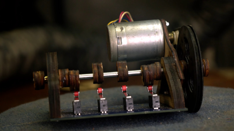
While a switch-mode converter operates using PWM at many times the output frequency for efficiency, we’re guessing that most readers will be familiar enough with how AC works to see how a low frequency converter turns DC into AC. A set of switches repeatedly flip the polarity, and the resulting square wave is fed into a transformer to step up to the final voltage. The switches can be mechanical as with old-style converters that used vibrating reeds or rotary armatures, or they can be electronic using power transistors. In this case they are a set of microswitches actuated by a set of cams on a shaft driven by a small motor, and the transformer comes from a surplus UPS.
We’re guessing that the frequency will be only a few Hz and the microswitches will suffer from switching such an inductive load, but as you can see in the video below the break it does light a mains bulb, and we’re guessing it would be enough to activate most wall-wart switching power supplies. We’re not so sure though about his use of the IEC sockets from the UPS to carry 12 volts, as the current may be a little much for them.
Meanwhile if you thirst for more of this kind of thing, we have you covered.


Those switches will burn up in no time. Also, that 50Hz transformer is not going to be very happy running at such a low frequency. It’s probably saturating and drawing a lot of current. It would work a lot better with optical switches driving MOSFETs so it could run at 50Hz.
I made a rotary encoder using 3 roller switches and 3 cogs to turn them. it didn’t work for me because i guess i was using the wrong shape, should have used a cam instead for a gentler slope to get them to switch reliably.
back in the day there used to be tube car stereos that used a relay vibrator to generate the high voltage. that would be a better approach.
I experiment with this concept some years ago using four carbon brushes and a commutator stolen from some scrapped appliance. The brushes were spaced 90 degrees apart… power goes in at 12 and 6 o’clock, “AC” comes out at 3 and 9 o’clock. The commutator is wired to create two, opposing, somewhat-less-than 90 degree arcs.
With this arrangement, you get four polarity changes (two electrical cycles) per rev… meaning, to create 60-cycle AC your commutator need only spin at 1800 rpm.
Now here’s a neat trick if, after running the AC through a step-up transformer and should you need to convert back to DC: Add a second commutator and a second set of four brushes… this same arrangement can be used to synchronously rectify the AC back to DC… provided the second commutator is indexed properly with respect the first commutator (the one producing the AC).
I’m not saying there is any advantage to this over a solid-state inverter. There is a lot of sparking, friction, and wear. But if you’re talking MacGuyver, the carbon brush approach will indeed create a usable electro-mechanical inverter… certainly one more practical than a design with cams and micro-switches.
Oh… for extra credit… use a couple of stacked aluminum pie tins (separated slightly with glass stirring rods, the lower having been filled with a solution of washing soda) and make your own electrolytic capacitor filter cap. I have books showing a more elaborate implementation of that idea–a dozen tins, stacked and filled as described, then immersed in oil–used for filtering high voltage DC for early transmitters.
I love impractical but simple projects that demonstrate the fundamentals in a tangible way! Salt water caps are still used in the Tesla Coil community as the most expensive component of Spark Gap Tesla Coils(which Marconi used for his first radio and Tesla didn’t enforce his patent much to Westinghouse chagrin) is the capacitance. The most refined design is a 5-gallon plastic bucket using glass beer bottles filled 3/4 with salt water(Tesla used wine/champagne bottles), place in bucket and fill to same level with salt water. Place copper wire in each glass bottle to meet at top as one electrode, and several more throughout the bucket as other. Fill remainder of glass bottles with mineral oil (or other non-organic insulating fluid) then the bucket up to the the screw top threads of the bottles, route terminated electrode bundles through bucket lid(spaced apart to prevent arc over) and you have a cheap and robust high volrage cap that is sufficient for a Neon Sign Transformer driven Tesla Coil.
All the people in this thread slamming this article as pointless when Solid-State inverters exist are missing the point of this site IMO. The video is a demonstration of how simple an inverter could be, allowing one to create a useful version if the need ever arose just by understanding the concept. It’s like making an electromagnet out of 20 turns of wire around a nail. The point isn’t to have the best electromagnet, it’s to simply and cheaply demonstrate the concept that underlies every other electromagnet.
The video is 100% fake. The output can’t be a square wave but pulses as electromagnetic induction requires variation of voltage to occur, and a switch generating a square wave in transformers input will become high voltage pulses on the transformers output, therefore the power density even though it is generating phase shifted pulses will be so low that it will never be able to power a drill or any other tool.
Also, the motor+switches contraption is way overkill; if you want to build a step up generator, you can pick a relay and use its NC contacts to drive both its coil and the transformer primary coil. For very low currents you wouldn’t even need the transformer as the back-EMF from the relay coil would be more than enough to generate higher voltages to drive small loads. This is how step up inverters were made a century ago and used often in first ancient car radio systems where tubes would need hundreds of volts.
While there may be some unanswered questions the OP clearly states the video is there to learn some things, not to replace the existing state of the inverter art.
To comment “this video is 100% fake” is just ignorant. I’d almost see your comment as a LLM-generated summation of the previous comments, due to its lack of originality, but the LLMs typically have safeguards stopping outputs such as your opening line!
This video is clearly a hack that does something that the materials were never intended for and works only sort of… Which is what we’re all here for.
Fake or not, this video is an advertisement that contains 100% silliness and 0% hack.
No, it’s a doctored representation of what might happen if a youtuber could bend law of physics enough to turn something that is indeed true in principle (DC+switch+transformer=high voltage) into something that can actually drive a load like the one showed in the video. Just look at the battery current or solar panel size and do the math: they couldn’t drive a drill even without the conversion induced losses.
The web is full of junk like this and pretty much every crook trying to sell the latest “magical gadget that will make you save thousands” is using the same trick: a principle that is indeed true in theory, but doesn’t scale to be usable in real life, be it the €500/meter audiophool cable, or the power factor corrector to stick into a random mains socket, a pocket ionizer to kill Covid-19, and of course the batteriser, solar roadways, and similar rubbish again and again.
Speaking of doctored, I can’t help reading your reply in an angry Scottish accent
We used to have 12V DC motors on a spindle with a generator winding colocated, and turning out 150 or 600V DC on brushes at the commutator at the other end.
Plus howling as a banshee might.
If you had slip rings rather than commutators you’d automatically be putting out pure sine WAVE AC.
That shaft is running at far less than 50Hz, the only reason he’s getting the bulb to light up is because it is a device which could run as happily from DC (and lower voltage DC at that) as it can from 220V AC. This will not work to power an appliance which requires actual AC in the approximately 50Hz range. Furthermore, even if his shaft was faster, his motor looks a normal DC one (the extra wires may well be encoder related) so it will seriously slow as extra load is applied. If he wanted a reliable AC frequency he’d need a motor of some form which was already being driven by synchronous, or asynchronous, AC. You can get 12V AC motors for things like turning a disco ball at a constant rate determined by your AC input frequency, but you’d do better with a solid state switching circuit by far.
Wouldn’t it be better and easier to have a motor spin an alternator?
It works as planned however the effect of back EMF as the transformer is being driven will be too much for the switches to bear leading to hot contacts that will eventually burn the switches. This effect might be low at small loads or free runs but will increase as loads are being applied.
A capacitor might be required at the output terminals to smoothen the AC voltage produced as it may be very harmful to certain inductive loadings.
Since there is no mechanism controlling the speed of the driver motor, speed undulation is expected as load varies also adding to the woes of the setup.
Reminds me of an ancient device from Germany here, which was being called an “Umformer” (it may translate to transformer or converter but these are different devices. I mean the electromechanical device).
The principle design consisted of two different electro motors or one electro motor and a dynamo, each coupled with the other one through gears, belts or an connection rod.
By combining AC and DC motors, AC and DC could be transformed.
This was before transformers or rectifiers were available for certain applications.
The compact models were one single unit, sharing one axis of rod.
They were in use in petrol stations, I think and converted 12V DC to 220V AC. And vice versa.
Speaking under correction. That’s what I remember from my ancestors’s stories. :)
The rotary inverters I have heard of are called Redi-Line
Yes! Had one from princess auto way back. For some reason I associate it with my Rota-Phase.
As a teenager, when tube type car radios existed. I took a car radio vibrator and connected it to the secondary of a 24v center tapped transformer. It produced usable AC on the primary.
I came here expecting to read about something bought from Temu.
This discussion reminds me of what I consider the ultimate electromechanical hack:
Just before DeForest and Fessenden developed workable vacuum tubes, Western Electric was working on mechanical amplifiers about 1912 or so, according to The History of Technology in the Bell System, vol 1. A voice coil was connected by a rod to the diaphragm of a carbon transmitter. Carbon transmitters have an effective power gain of up to 50. That’s why telephones got much better and more practical when Edison invented the carbon transmitter. The mechanical amplifier had heat sink fins because a quite large current was run through its transmitter.
The book above also describes a technology demonstration where a political speech was relayed to distant audience using no more than a carbon transmitter and large horn speakers at the other end. Special extra thick aerial conductors had to be run between venues and the microphone had to be water cooled because it was carrying something like 6 amps current.
You could just use a dpdt relay
One pole is wired normally closed and the input to a transformer is wired to the other pole normally open
This causes the relay to oscillate, and you rely on the inductive kicks to give an ac voltage, pulsed DC works on a transformer it’s technically ac at that point
That’s effectively how old cars used to produce the spark for ignition
Hahaaaa, LoL, by-by, micrprocessors, SPWM, mosfets, shoot-thru issues, etc . . .
Just plain micro-switches will do, and and some more, as to smoothen out ;-?
That’s why 12-cylinder engines were developped ;-)
Even better, use the same mains voltage plugs and sockets for the 12Vdc input, great
Waiting when someone plugs in a real household mains plug into that part, . . .
You’re solar panels will start giving of light, motor will spinn at thousans of RPM,
and you’ll lift off the Earth, LoL ;-?