While classroom learning isn’t for everyone, one awesome benefit of the Internet is that you have a variety of college classes available to you, even if they aren’t for credit. You can virtually audit classes from institutions around the world on just about any topic you can think of. Of course, the topic we think of is practical electronics and that happens to be the title of a class from [Dr. Bill Newhall] of the University of Colorado. You can watch the first part in the video below. So far, there are two lectures available but more are coming as the class is ongoing right now.
[Dr. Newhall] is one of us. He’s a ham radio operator and a pilot, as well as an electrical engineer. This class is aimed at others who need to understand electronics in another context. It reminded us of the genesis of one of our favorite books — also from a professor — The Art of Electronics.
The course material promises to cover topics ranging from solar and battery power sources, power conversions, IoT and RF communications, sensors, and DC motor control. Of course, there will also be sections on microcontrollers and associated hardware.
Just like a real class, the first lecture has a lot of housekeeping information, but you might want to skim it anyway. But if you want to get to the electronics, the second video won’t disappoint. While it covers a lot of ground that is probably familiar to most Hackaday readers, it is a good review and there’s more coming in the future lectures.
With all the resources online, you can easily hack your own degree plan together. Having access to instructors like [Dr. Newhall] is exactly the point we were making about how the Internet allows you to leverage the best educational opportunities no matter where you are.


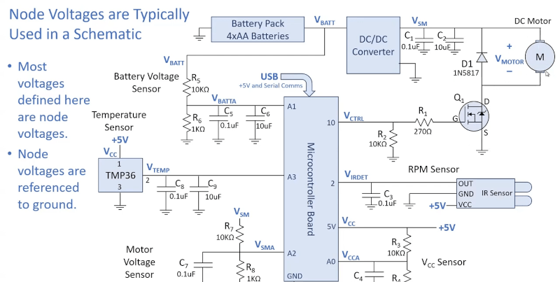
I can’t help but cringe when I see a schematic without connecting dots AND with 4 way junctions. These are not good practices.
I never understood why people are against just always putting the dots. The dots cost so incredibly little and remove any chance of confusion. I prefer dots even in 3 way junctions where the connection is implied, it just doesn’t hurt.
Maybe the late 1990’s turned us against dots (com).
Dots are absolutely required if you’re adhering to the international standards (eg IEC60617) – that explicitly says that if two lines cross, they’re not connected unless there’s a dot. Even the US-only ANSI Y32/IEEE 315 standard from 1975 says that if there isn’t a dot, it’s not connected. A dot is not required when a wire doesn’t cross another, but just ends at it.
What is jarring to me is the use of zigzag resistors. I know they’re allowed in IEC60617 – but they’ve been discouraged by the IET (IEE) and other organisations outside of North America since the 1980s. They look very old-fashioned to me, like I’d expect to see on the circuit diagram for a 1950’s radio. Also when hand drawn, they can get lost or turn into inductors :( Perhaps because I did my electronics degree in the early 1990s in the UK, I much prefer box resistor symbols.
However I’m happy to tolerate archaic symbols and connection styles if the literature they’re present in predates the standards of course.
In 1875, the United States solidified its commitment to the development of the internationally recognized metric system by becoming one of the original seventeen signatory nations to the Metre Convention.
Source:
https://en.wikipedia.org/wiki/Metrication_in_the_United_States
Apart from that, I like my boxy resistors because you can put the values inside them. I use KiCad, and I find that the default resistor (with the value inside it) takes up less space then the “small” resistor, with the value next to it.
RKM code is also standardized and easy for quick / short notation.
https://en.wikipedia.org/wiki/RKM_code
This old guy loves zigzag resistors.
“I’m a man and I can change, if I have to, but I don’t want to.”
-Red Green
I was told (by my engineer boss at the time), you dont use dots because when you make copies of your schematic, the copier will automatically “add” dots through bluring.
It was true on copiers (especially fax machines) used at the time.
So, no longer needed, but carried over from “old school”
Long time EE here… may I weigh in?
I loath dots…. not because it hurts to have them, but because it hurts when they go missing (when legacy prints are scanned or photocopied, for example.) If that doesn’t threaten their existence, old age and poor eyesight effectively does (trust me.. you’ll eventually get there).
So how to deal with cross-overs vs four-way connections? Easy, with two simple rules: First, ANY place where two conductors seem to form a “+” is automatically presumed to be a cross-over. Second, if you MUST connect four wires together, you stagger the joint like this:
|
—|
|—
|
With this practice, whether you choose dots or no dots (and whether or not they are properly reproduced in copies or prints, or whether or not you can see them ), it doesn’t matter, the two conditions are unambiguously differentiated.
I avoid dots in schematic resistor values for the same reason. I never say “1.2 K,” rather, I say “1K2” Unambiguous meaning, that does not rely on dots.
Grrr… my ascii art didn’t translate well after HaD formatting…. Hopefully you catch the drift.
Yeah, I prefer the staggered way.
If your copier is such crap that it can’t retain the dots… I doubly doubt its retaining the lines correctly either.
Ohhh, ok so to make a long response thread endless…
I learned all this in the 70’s/‘80’s but got away from the hobby. Later I always wondered why the 1K2 was written that way, totally makes sense now. Oh and whenever I crossed lines that were not meant to connect I gave one a little semi-circular “hop” ;) I may have gotten that from old Popular Electronics mags.
Very poorly drawn schematic…makes one wonder about the rest of the content…
“Just like a real class” : It IS a real class.
Well, meaning just like sitting in a classroom…
Without whispering from people sitting near you.
I like the videos but I kept wanting it to jump into a practical lesson or lab session. I know that basic definitions need to be laid out in advance but I always enjoyed the physical side of hooking things up.
(Old joke – Long ago, before the days of email, I took a home correspondence course in electronics by mail. One day I had a question so I wrote the teacher. They mailed me their reply…..”please put your hand down….you may go to the bathroom”.)
“Sheldon, it’s college. Just go!”
This is great. Online learning is one of the indisputable benefits of the Internet.
Ah, “The Art of Electronics”. While I struggled through reams of calculus while studying EE, friends in physics were taking a compact one semester electronics course that gave them more practical, applicable electronics knowledge than I had received in two years. And The Art of Electronics was their textbook.
You commented that very same short story on the “The Truth Is In There: The Art Of Electronics, The X-Chapters” HaD article 4 years ago. Though I like the most recent retelling.
The Art of Electronics and the X volume are very good reference books which deserve a place in an electrical engineer’s or electronics technician’s library. The writing style is concise without being stuffy or pedantic.
I would also like to recommend Handbook For Sound Engineers edited by Glen Ballou. Don’t let the title fool you, this is a substantial reference text that is applicable to engineers who work in small signal and even RF domains. There’s even material applicable to illumination, room acoustics and power distribution. I’ve found material in there about topics such as why one choses specific wire types, insulating materials and construction techniques that I’ve never seen in a classroom textbook. The price is quite affordable if you purchase one or two editions back from the most current edition. There aren’t huge changes from one edition to the next.
As a runner up, I’ll recommend the Amateur Radio Relay League’s Amateur Radio Handbook. There’s a lot of solid information on design, construction, antennas, RF propagation, etc. You don’t have to be interested in ham radio to get value out of the book. The text is a good fit for people who are math averse because it mostly sticks to basic algebra and generally avoids calculus. The information doesn’t change markedly between editions, so there is not need to have the most current release.
Good recommendations!
But what if one is an unsound engineer?
B^)
Good pun.
It isn’t perfect, but I refer my students to the AllAboutCircuits web site if they fell they aren’t getting all of what they want and need from the class and textbook. The site covers basic, DC and AC circuits, power circuits and digital logic. There are fairly well curated lessons and there are practice questions to check proficiency. Over all, it is a nice resource.
Make that “… they feel.”
I’m not impressed with these videos. In the second video, 45 minutes in, even he’s confused about the numbers in “calculating energy delivered to a load”. Maybe I skipped it, but I didn’t see the handy ohm’s law V = IR diagram in a circle with V being on top, and I and R being in the bottom two quarters. I just see a bunch of dry equations written out that are difficult to memorize.
“Practical Electronics.” Reminds me of the interesting day I found Lancaster’s “TTL Cookbook” and “CMOS Cookbook” in the college bookstore. Were they for some EE class that would finally get into practice instead of calculus, perhaps? How exciting THAT would be!
Nope. They for a graduate chemistry class, on building your own lab electronics…
Possibly the best non-calculus based electronics I’ve seen is from Jim Pytel on the Big Bad Tech Channel.
https://www.youtube.com/watch?v=UNZKlCoDxmY
I FINALLY understand Thevenin equivalent and how to calculate it.
And the dry humor is delightful.