Everyone loves, and should respect, lithium-ion batteries. They pack a ton of power and can make our projects work better. I’ve gathered a number of tips and tricks about using them over the years, based on my own hacking and also lessons I’ve learned from others.
This installment includes a grab-bag of LiIon tricks that will help you supercharge your battery use, avoid some mistakes, and make your circuits even safer. Plus, I have a wonderful project that I just have to share.
Hot-swapping Cells
When your device runs out of juice, you might not always want to chain yourself to a wall charger. Wouldn’t it be cool if you could just hot-swap cells? Indeed it is, I’ve been doing it for years, it’s dead simple to support, but you can also do it wrong. Let me show you how to do it right!
Recently, a new handheld has hit the hacker markets – the Hackberry Pi. With a Blackberry keyboard and a colour screen, it’s a pretty standard entry into the trend of handheld Pi Zero-backed computers with Blackberry keyboards. It’s not open-source and the author does not plan to open-source its hardware, so I want to make it absolutely clear I don’t consider it hacker-friendly or worth promoting. It did publish schematics, though, and these helped me find a dangerous mistake that the first revision made when trying to implement LiIon battery hot-swap.
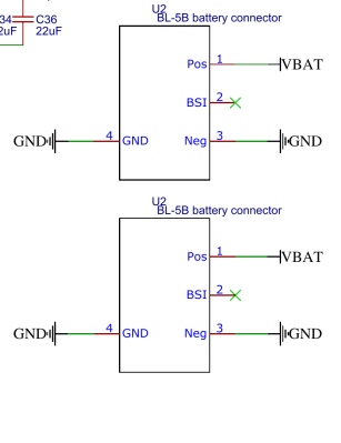
It uses BL-5C cells, which are widely available as aftermarket batteries for Nokia phones. It’s a smart choice, though it’s worth remembering that vendors constantly inflate the capacity on the label, and my gut feel is that the more inflated the number is, the more shady the cell you’re getting. Remember, there’s a physical limit to the capacity you can shove into a certain cell volume, with 18650s limited to about 3500 mAh, as the market offerings show. (And if you try to put more capacity into a cell of certain volume, you get the Galaxy Note 7. Ahem.)
The batteries in the Hackberry Pi should be hot-swappable – no supercaps, they’re just in parallel with nothing in between the cells. Nothing in between? Question – what happens when you connect two batteries, one charged and one discharged, in parallel? Remember, LiIon batteries can give out a ton of current, and phone batteries doubly so due to the GSM modem peak current requirements. Decent voltage difference, very low resistance – you get a lot of current flowing, discharging the full cell needlessly or causing a brownout at best, and charring PCB tracks at worst.
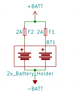
The easy solution is to use PTC resettable fuses in series with the positive or negative terminal, either between each cell, or just one between two cells. If current surges sharply, the fuse will heat up and increase its resistance, limiting the current.
But remember, a fuse’s current rating is deceiving, and a 2 A fuse won’t actually trip at exactly 2.1 A. This is beneficial for you, though – while doing hotswap, one cell will have to produce twice the current than normally, even if for a short moment. Also, remember to size the cell protection fuse not just for device consumption, but also the charging current it will receive!
It’s certain that the new Hackberry Pi revision will fix this, and if you have the first revision, just swap batteries carefully and you will be 100% fine. Hotswap doesn’t have to be complicated – now you all know how to do a very simple form of it. Oh, and, having adding the fuse, you can easily get a good few extra features with only a few components, like, say, polarity protection!
The Polarity Hacks
With 18650 holders, it’s easy to insert a cell the wrong way by accident – I’ve burned out a good few boards like that, spending precious hours and dollars replacing burned out components. A 18650 cell holds a ton of energy and can burn out a lot of silicon very easily. Or if you’re using pouch cells using JST-PH connectors, you have to watch out for two polarity conventions. In short, polarity reversal is a real risk. How do you protect from it?
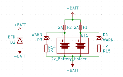 The reverse polarity crowbar circuit is a dead simple way to add polarity protection – all you need is a diode across the battery, placed after the fuse, flipped in a way that it will conduct when the polarity is wrong, tripping the fuse before any circuitry is damaged. The diode’s rating has to be higher than the fuse’s trip point – otherwise, the diode will burn out before the fuse trips, negating the circuit. I’ve tested this, it works, it’s now being manufactured in hundreds.
You might also want the user, whether you or someone else (especially someone else!) to quickly notice that the polarity is flipped. The solution is simple – add a LED and a resistor flipped in a way it lights up when the cell is reversed, before the fuse. Use a red or orange LED to make it crystal clear that something is wrong; don’t use green or blue, or any colours that often mean “the device is working normally”; add silkscreen markings to indicate that this is a “wrong polarity” LED.
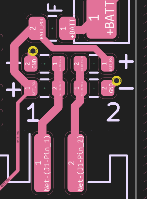
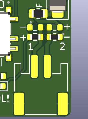
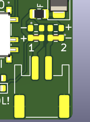
Back to cells with JST-PH connectors. Are you developing a project that will get into hackers’ hands, and you don’t want to have them rewire their entire LiIon cell arsenal just for your device? Thankfully, 0 R resistors save the day; it’s dead simple to add two pairs of 0603 0R’s next to a JST-PH 2-pin connector. Make one polarity the default, and leave the option of switching the polarity in there. Again, this goes before the fuse, and before the reverse polarity LED, too. Of course, your users will have to make sure the red wire goes to positive, but at least you’re helping them get there.
This quickly, we have dealt with a number of polarity problems, using barely any components, all of them cheap, no fancy ICs. Your boards deserve to be fail-proof, serving you no matter the mistakes you make.
A New 18650 Holder Enters The Scene
Leaf contact holders are great. Unlike spring holders, they’re low-inductance, high-current, resillient to shocks, reliable, and cheap to find. Unfortunately, the leaf often catches on the cell’s heatshrink ends when you unplug the battery, slowly tearing it off piece by piece, and at some point even causing the positive terminal protective ring to detach – which risks a massive short-circuit as you unplug the battery or just drop the holder hard enough. Not great!
I’ve developed a pretty unique holder for 18650s, that I currently use for a pretty substantial portable device project of mine. It’s got all the advantages of spring holders, but it wraps around the battery fully, protecting it from shocks and the elements, and closes with a twist-on locking cap. Plus, it’s belt-mountable, thanks to a 3D-printed holder. It lends itself wonderfully to hotswap, too! Most of all, it’s fully 3D printable. All you need is some threaded inserts and some leaf contacts from Keystone that I found on Mouser – a baggie with 25 of them is quite cheap, and worth the money. (Remember to scroll through categories for things like battery contacts, you will find cool stuff!) There are definitely drawbacks to this type of holder, but it’s seriously great.
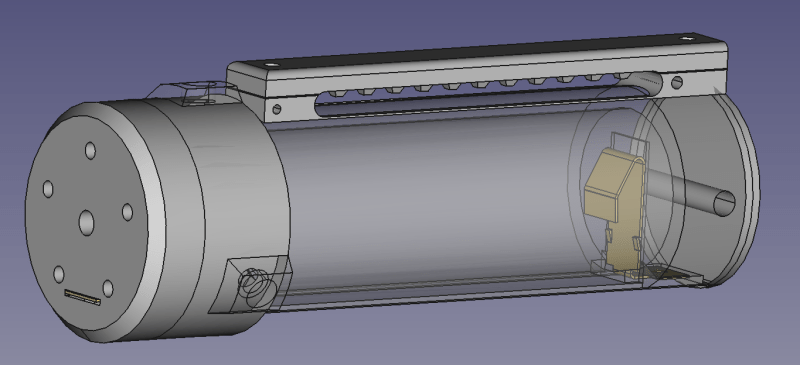
It’s parametric, designed in FreeCAD, so you can change a fair few parameters without breaking a sweat. The holder is designed for quick swap – just twist the cap and the battery falls out. Swapping 18650 cells is a cakewalk. High current consumption: tested; portability: tested; not damaging the cell wrappers: tested. I’ve been actively using these holders for about nine months now – they fulfilled their purpose and far more.
There’s something that makes it feel like military equipment, but I can assure you that it’s not designed by the lowest bidder. Put these on a belt, screw these into a project, or slap two of them together back to back – maybe even lengthen it and use three cells in series! Thanks to someone’s advice from Twitter, there are also vent holes at the positive terminal’s place. (Of course, if your cell starts venting, you have a big problem on your hands no matter what you’re using.) Still, it’s got these holes, in addition to ten other features. And it’s printable vertically with no supports.
Are there possible failure modes? Absolutely. The main one is the cylinder breaking across the layer lines under pressure, especially if you drop it. I’ve tried printing the holder laying down, so that layer lines are aligned differently, but cleaning the tube from internal supports is damn brutal and the tolerances for the 18650 inside are pretty tight. I’m going to pick up a roll of PLA-Plus, since it supposedly is more strong, and print a new set of holders. If you print it, let us know!
Another failure mode is the springs compressing over time. I might be overcompressing the metal, so I just ought to check the datasheets and adjust the width. Of course, strong compression is a plus, but it’s of no use if the holder starts being super bump-sensitive after a few months of use. Last but not least, the positive wire is a failure point, though the channel i’ve recently introduced mostly fixes that.
More To Come
There are a few additions in the queue for the v3 holder. One is unifying the threaded inserts so that you don’t have to buy too many different ones, and improving mounting for the belt holster to limit the molten plastic backflow. Another is adding strips on the side that’d be a base for a long metal plate, which would acts as extra backing for the 18650 holder. The only problem is finding a suitable metal plate – flat, 70 mm long, about 4 mm wide, with screw holes alongside, or, at least, on both ends. Anyone have any ideas, especially if it’s something commonly found that can be repurposed?
I’m currently working on a custom PCB for this holder – involving protection, fuse holding, reverse polarity protection and warning LED, and maybe even an opamp circuit for roughly measuring the battery voltage. In short, including all of the tips shared here.
What are your favorite tricks for using lithium batteries?


Page not found on the github link for the battery holder…
yeah, I kept it on private and didn’t notice, think I set it to public a minute-two after your comment!
“In short, polarity reversal is a real risk” :D
Co-opting top comment about polarity reversal:
You can swap contacts on just connectors fairly easily. Just use tweezers or something tiny to depress the little metal tab that holds the contact in while pulling gently on the wire, and the contact pops out undamaged. Might need to bend the tab back up a little bit.
Pull them both out and swap them, and its as good as new! Only takes many a minute.
Looks like the reason for the discrepancy is that in the rc world, the polarity is usually one way, and in the arduino/sparkfun/adafruit world, it’s the other way. Idk how that came to be, but it is.
Standards people! They’re a good thing!
Good tips though on building a device that won’t fry if one gets plugged in backwards.
Standards for polarity are a GREAT thing! That’s why we have two of them.
This seems like the place for me to complain that 18650s don’t have sufficiently distinct positive terminals (like on AAs for example), which is a regular micro-irritation.
And while I’m dumping battery thoughts: I’m about to build a thing that uses DeWalt “20V” battery packs, as they’re super simple and you can easily get physical holders that just break out the + and – terminals. However, I would like to add overcurrent / undervoltage protection, and maybe even use the battery pack’s handy thermistor pin. I know I can buy an expensive holder with those features, but does anyone know of a nice, simple, ready-to-use published circuit?
If you’re already invested in Dewalt tools and batteries, it may be worth the extra work on the device side.
But from a clean slate, I’d go with Ryobi or Ridgid instead — two of the few brands that implement low-voltage protection on the battery side instead of the tool side.
You want a 5s battery management ic. It’ll watch for overcharge, undercharge and pay attention to each individual cell to make sure they are balanced (so a cell doesn’t charge above 4.2 even if the whole pack is still not fully charged)
Looks like Dewalt batteries break out all the balance leads, so it should be a pretty easy connection to make.
I’ve used the bq77915 before, and it works well. Uses external mosfets so you can set it to trip at a fairly high current if needed.
not just that, don’t forget, you can also buy pre-assembled 5s protection circuit boards on Aliexpress, quite a few have balancing included, too!
oh these batteries don’t have a protection circuit? That’s weird, ngl, don’t know if this decision is a wonderful one. Overcurrent and undervoltage is firmly within the purview of the protection circuit. As for thermistor management, a charger worth its salt should have the option to wire one up – it will only be accounted for during charging, but that’s most of the time when you want to monitor the temperature.
Those batteries only cost $150-$200. If they put proper protection in they might have to double the cost.
(https://www.homedepot.com/p/DEWALT-POWERSTACK-20V-Lithium-Ion-5-0Ah-Battery-Pack-DCBP520/319702237)
They did put in low voltage fuse in the pack so if it gets too low even for a moment the whole pack is bricked. I’ll leave it to the readers to figure out why they did one but not the other.
also, about non-distinct terminals – yeah, it can be an issue with some cases! I’m thinking about lengthening this holder for a 3s configuration (== a “long tube with cells” kind of deal), to get ~12V for some LED strips, but mostly as a fun experiment. Now, I’m wondering if I’ll have to include thin disk magnets in between the cells, just to make sure there’s enough physical contact between the + and the – terminals. On the other hand, the flat + terminals do make spot welding more convenient than it would be otherwise!
Do you have any suggestions on how to build something equivalent to “trickle charge” with an existing battery eg from a laptop?
One of my use cases is act as a ups-like thing for a mini Pc which is powered by an external 19v power brick.
Thanks for all the replies! I should have mentioned, I only want to discharge these things, but BQ77915 is still a good suggestion (esp. since TI parts tend to have good documentation). And it is useful to know Ryobi have protection circuitry inside their packs (though I am already in the DeWalled garden).
DeWalt packs just have the + and – contacts always live, so they literally couldn’t be easier to use, and I was thinking of that as a plus. But on reflection, if I have any trouble rolling my own battery management, I’m likely to skip it, and maybe regret it later. And Amazon is full of $5 adapters to use these things in ride-on toy cars, which definitely won’t have any safeties. So it maybe isn’t perfect for DIYers after all.
(Of course, when manufacturers put ICs in their batteries, that doesn’t mean they need to add DRM).
(Also, agree on a standard format already)
Hi! Just wanted to let you and the other viewers hear that I had recently swapped out some dying 18650’s on a dewalt 20v max pack. The odd thing was that one of these Samsung batteries has a reverse polarity compared to all the other batteries. I’m not sure if it was depleted and installed backwards causing premature failure, or it was just manufactured defectively. Either way, always double check the polarity with a multi-meter. If not, the results may be shocking lol
A long time gripe: with as little as 2 cells in series the saving of a little bit of wire and having both ways of insertion, instead of all cells in the same direction. A zigzag of wires behind the pack vs. having to zigzag in your head and hands every time you load. Which way first? Poof!
As said in poor translation on a wall outlet plug-in 18650 charger I had with 2 cell holders in plus-up positioning, “forbids to invert”. With 3 prong ground up “woke” outlets it’s inverted.
Took me a bit to understand what you are saying, but then I realized, you’re talking about multi-series configurations with standard holders, where you can either have them all face the same direction (which requires running wires across the holder), or alternate the directions (which lets you join adjacent contacts with short lengths of wire). IMO, spending more wire on “facing the same direction” is indeed 100% worthwhile – all cells facing the same direction is just that much more intuitive of an approach for me and for my devices’ users, so I will go for it any chance I get; “which way first” is indeed a problem you don’t want to be figuring out when swapping cells.
It’s pretty annoying to me that holders like Keystone 1048 assume alternating configuration, with + and – imprinted on the plastic in an alternating way – if I wanted to sabotage products my holders are used in, that’s the kind of imprint I would add. In fact, these alternating imprints were the sole reason that I had someone short-circuit two 18650 cells in reverse to each other on the ZeroPhone battery board, which used the 1048 – that’s when I started looking into PTC fuses!
I’m not a fan of 0-ohm resistors. If I ever have to hand solder that I will be very annoyed that it wasn’t a proper solder jumper.
The JST-PH de facto polarity standard is universal enough that any battery doing things differently should… Not do that. I think a better solution would be to make a crossover cable with a PH male to female extension, to allow all your batteries to have the usual pinout.
I definitely do kind of wish I’d put polarity protection on my latest PCB, even though I’m not sure space would allow.
Not sure why it’s not just built into battery protection PCBs. You need an external one anyway, since if you put it on the board itself, it might not turn on when you connect a battery, until you apply a charger.
Problem is, the polarity standard is not universal enough – there’s one in the West, and the opposite one in the East, from what I’ve seen. It’s not something we can really change, so we have to watch out for it. You can change polarity very easily on a battery, only need tweezers or a needle, but you have to watch out for the polarity aspect unless you want to be accidentally killing boards as soon as you plug the battery in.
The “might not turn on until you apply a charger” applies to protection circuits no matter where you put them. A good idea is to put a protection circuit as close to the cell as possible, ideally, paired to the cell, and not duplicate them without need. Protection circuits don’t block reverse polarity because they’re meant to be paired with cells – which does break in the “18650 in a holder” situation where you can reverse polarity and accidentally kill your protection circuit, but, my guess is that it’s a fringe enough case and the IC makers don’t want to account for that.
Why would you go to fuses before diodes for polarity?
If you put forward fuses, you will loose some voltage and waste power during normal operation.
The reverse diode and fuse will only act when on reverse polarity.
I think a picture of the polarity reversal by 0ohms trick could have had a picture for those of us that are more of the visual territory :)
hmm do you not see a picture? There’s one embedded in a gallery. Or did you mean a specific kind of picture?
Regarding ~3.5 Ah cap for 18650s, there are reportedly fair 4 Ah cells by vapcell and cheaper liitokala-branded stuff with huge variations in capacity but way cheaper (idk, mb fine for 1s use cases like flashlights)
@Arya Voronova said: “The batteries in the Hackberry Pi should be hot-swappable – no supercaps, they’re just in parallel with nothing in between the cells. Nothing in between? Question – what happens when you connect two batteries, one charged and one discharged, in parallel?”
One way to make the two battery packs hot-swap is to diode-or them (you show a simple example of this), but ideally use MOSFET-based “Ideal” diodes with a near-zero forward voltage drop. An even better solution is to use a load balancing battery management system (BMS). But I found a true 2P balancing BMS chip is tough to find (try it).
I don’t show a simple example of diode-OR – this is fuse-OR at best =D You can’t really use non-ideal diodes, because the voltage drop is big enough, you will waste energy and you will lose out on useful capacity unless you use a buck regulator, something that tends to introduce more waste than benefits in a typical usecase. It’s also not clear to me how well ideal diodes will behave once the batteries are equal-voltage-but-not-quite – I’d be worried about some fun oscillation occurring. I’m yet to see a load balancing BMS, and I am not holding my breath – everyone parallels cells and nobody accounts for hotswap; if you want to do load balancing with two cells, from what I’ve seen, you have to improvise.
For the spring compression you could place a battery stop bump next to it, so that it takes the compression force, while the spring is mounted so it just has the rated compression for contact.
(hmm, the last few weeks I was able to comment on my old laptop, now I have to use the auxiliary phone again … was there an update undone?)
ooooh I like this! the problem with the bump is that the contacts have to be momentarily compressed more than usual, because of the latching mechanism. My bad on not adding better pictures of the holder mechanism, though, gotta look into it!
Perhaps a harder spring next to or around the contact spring instead of the bump may do the trick; if the latching is done by the hard spring on one side, you may get away with the rigid bump on the other side.