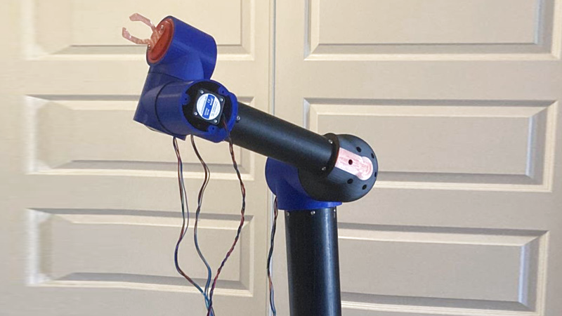
[Leo Goldstien]’s entry into the world of robotics has been full of stops and starts. Like many beginners, he found traditional robotics instructions overwhelming and hard to follow, bogged down with dense math that often obscured the bigger picture. So he decided to approach things differently and create something with his own hands. The result? A 3D-printed robotic arm he affectionately calls “ManiPilator.”
This article is the first in a three-part series documenting [Leo]’s hands-on approach to learning robotics from the ground up. Building ManiPilator became an opportunity to learn by doing, and the project took him on a journey of experimenting, failing, and eventually succeeding in tasks that seemed deceptively simple at first glance. Each hurdle provided him with insights that more traditional learning methods hadn’t delivered. Below is one of the videos [Leo] captured, to show one step in the process: doing a check using multiple motors.
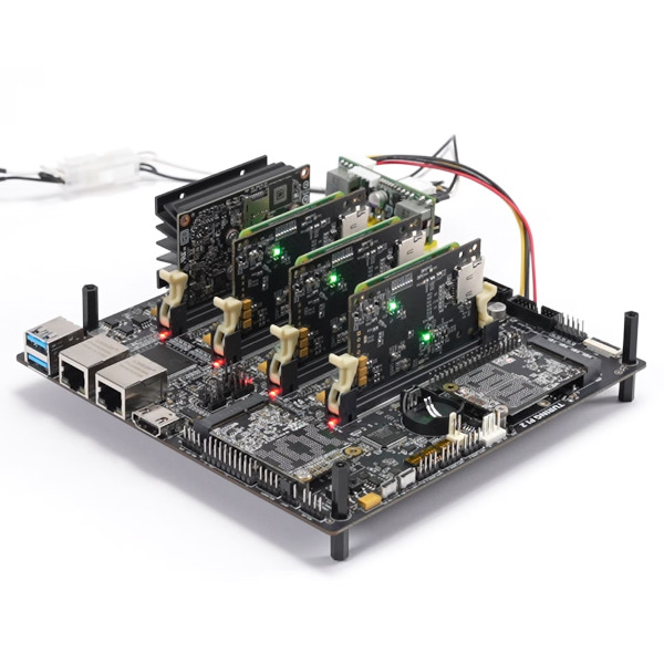
To make his project work, [Leo] relied on open-source software like Klipper, piecing together code and hardware in a way that made sense to him. In sharing his story, he offers fellow beginners an approachable perspective on robotics, with practical insights and candid reflections on the challenges and breakthroughs.
[Leo]’s project shows that there’s more than one way to start exploring robotics, and that sometimes the best way to learn is simply to dive in and start building. Follow along with his journey as he tackles the complexities of robotics, one step at a time.


Yeah. Forward and inverse kinematics, Jacobians, DH parameters and all the other sutff is a bit PITA to learn and later implement in MATLAB… but becuase we actually took the effort to understand it, we don’t tend to waste our time building cargo-cult versions of UR-5.
So instead you …?
Totally agree with your comment, Peter. All those are a PITA, especially when tackled outside of a traditional, structured learning environment. My intent was not to dismiss the intricacies of the subject, but to provide a gentler introduction through practical examples—an approach that has worked for me in the past.
As for the comment about cargo cults, I beg to differ with your opinion. If it looks like a duck and quacks like a duck, without evidence to the contrary, it might be able to fly (for a context-appropriate definition of flying).
If you’re willing, I would love for you to highlight some other 3D-printed designs that would have been a better choice.
I’m a little confused by the cargo cult reference. If the arm actually works… (which it certainly appears to), how exactly does that constitute being a cargo cult of an actual working arm?
And for those of us who don’t have the luxury of a MATLAB license… I’d suggest using “R.” There are some excellent papers and code on the topic. https://www.google.com/url?sa=t&source=web&rct=j&opi=89978449&url=https://www.researchgate.net/publication/372824631_Inverse_Kinematic_Algorithm_with_Newton-Raphson_Method_iteration_to_Control_Robot_Position_and_Orientation_based_on_R_programming_language&ved=2ahUKEwiS1O6nq4uJAxUCLkQIHQgeKMIQFnoECBIQAQ&usg=AOvVaw3MVmK5z7GvQlywRBXCWuCN to cite one.
Excellent work and kudos to Leo for publishing his work.
“If I have seen further — but not much further, just a few meters — it is from standing on the doorsteps of giants.”
And some people learn better by returning to first principles. If you’re going to take that approach, starting with a known good physical design makes a lot of sense. Hardly seems like “cargo-cult” to me, and the dismissive tone certainly discourages others from trying to learn.
Thanks for standing up for a stranger on the internet. It’s appreciated! :-)
Skimming through the linked write-up and it looks like he is going with stepper motors with no mention of any sort of position sensor. So, that means, his robot is going to be an open-loop control scheme. While this has been proven to work and can be relatively accurate (look at most 3D printers), it does have the potential for accuracy issues. I would suggest adding some sort of sensor, even something as simple as a rotary encoder on the joints, to get some sort of feedback and make it a closed-loop control. Will help with accuracy, precision, and repeatability.
For even simpler, albeit less accurate, feedback, an IMU could be added to the end effector and used to verify moves are going in the right general direction, even if precise position verification isn’t possible. I think the M3D Micro 3D printers used this concept.
One could also add “home” switches to the joints for start-up and periodic (re)calibration.
Yeah, IMU would do, but that gets into that Jacobian math to utilize it. Home switches is how a lot of the 3D printers I’ve seen work and is a lot less math. Personally, I would just use either some servos with position feedback or if I wanted to stick with stepper motors like this design uses, then grab some that have the encoders built in. Depending on torque requirements, they aren’t too badly priced. Though, no matter what method you use, it all gets into control theory and its fun math.
An IMU on the end effector is a great suggestion! I’ll definitely consider it.
As for needing maths to utilize it, that’s part of the fun, isn’t it? I’m always in awe of what can be achieved by working through some math.
It seems I’ve given the unfortunate impression that I’m trying to avoid maths in this project at all costs, which was not my intention. Maths are great! In this specific case, I found it hard to push through the details without a practical goal. Building a physical object gave me the motivation I needed to keep trying.
Thanks for bringing this up! Drift, accuracy, and repeatability are definitely concerns! My initial intention to tackle drift was to rely on the TMC2209’s step skipping detection. It’s far from a perfect solution, but as you mentioned, 3D printers have come a long way with just such an approach.
As for accuracy and repeatability, I’m planning on adding a feedback layer using strategically placed cameras. It’s likely a poor choice, but it sounds like a fun challenge!
Cameras are interesting because they have higher uncertainty in the internal coordinates, but potentially lower in the absolute position of the head. At least once you have corrected all the distortions.
Hi Leo, cool project!
I’m curious, Klipper supports multiple motion systems already, have you considered extending the motion system to support arms?
I have! Based on my biased reading of the Klipper forums, there is little current interest in this evolution path. A few contributors tried to add this functionality (referenced a couple under “Honorable Mentions”), but it hasn’t made it into mainline Klipper afaik. Definitely take a look at those, if you’re interested.