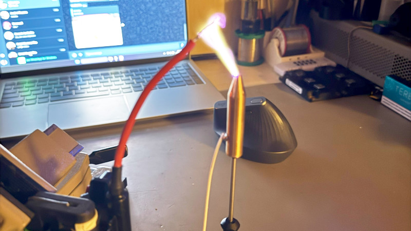
A common part used to create a high voltage is a CRT flyback transformer, having been a ubiquitous junk pile component. So many attempts to use them rely on brute force, with power transistors in simple feedback oscillators dropping high currents into hand-wound primaries, so it’s refreshing to see a much more nuanced approach from [Alex Lungu]. His flyback driver board drives the transformer as it’s meant to be used, in flyback mode relying on the sudden collapse of a magnetic field to generate an output voltage pulse rather than simply trying to create as much field as possible. It’s thus far more efficient than all those free running oscillators.
On the PCB is a UC3844 switch mode power supply controller driving the transformer at about 25 kHz through an IGBT. We’d be curious to know how closely the spec of the transformer is tied to the around 15 kHz it would have been run at in a typical TV, and thus what frequency would be the most efficient for it. The result as far as we can see it a stable and adjustable high voltage source with out all the high-current and over heating, something of which we approve.
Need to understand more about free running versus flyback? Read on.


I did something similar but with a quad op-amp, some transistors, and one 250v power transistor to drive the primary. The results was my custom flyback transformer and circuit produced a wide range of needed voltages and only draws 0.25 amps when no load was attached. One thing to remember is even the primary coil produces its own high voltage so its important to not waste that energy with a flyback diode or power transistor rated at too low of a voltage.
But can it play Megalovania?
The transformer is not necessarily optimised for a specific frequency, it’s optimised for a specific charge, which equates to a specific volt*second integral. If you exceed this critical value, the core will go into saturation, and excessive current will flow. On the other hand, if you lower the supply voltage, you can lower the frequency or increase the duty cycle (is there is any room left) to get to the same stored charge.
The important parts are not to exceed the maximum output voltage, by providing a path with a known breakover voltage, to prevent damage to the secondary insulation, and to limit the primary current, especially in the case the secondary side is sorted, and the stored energy had not been discharged by the time the next charge cycle begins.
Obviously, the core material also limits the maximum operating frequency, but that is usually not a limiting factor. You can monitor the core for excessive heating to determine if the frequency is too high.
Taking note of the pinout, while removing the transformer from its host, is a good idea; one can use the original primary that way (and ground any common pins — including the focus divider!). The downside is, it’s usually supplied from a modest voltage to begin with: perhaps 100-200V, so you need as much to run it outboard. If you wind wire around the “spine” of the core, you get poor coupling (bad for flyback; sorta good for resonant actually), but can pick your own turns ratio, making 12V operation or whatever feasible.
I did one of these a long time ago, with 555 and BJT flavor:
https://www.seventransistorlabs.com/tmoranwms/Circuits_2010/High_Voltage_Supply.png
The open-loop operation, in contrast to the UC384x family shown above, is acceptable given the “for benchtop testing” nature of most use cases. It’s how they’re originally used as well; the load is consistent enough that control wasn’t important. Of course, the BJT requires fairly strong base drive; in the original circuits, a transformer is used, but here a driver transistor and fairly beefy current-limiting resistor are needed. Primary snubbing as shown isn’t really meaningful, but a variety of things can (and something should!) be used.
I actually got this back out again, for once in a decade or so, to do some HV testing of materials and insulation for another project. How ’bout that!
Basically a smps driving a flyback?
I’ve seen that done before
Fly back done right is a holographic screen in mid space