It’s a fair bet that most of us have a ton of wireless doo-dads around the house, from garage door remotes to wireless thermometers. Each of these gadgets seems to have its own idea about how to encode data and transmit it, all those dedicated receivers seem wasteful. Wouldn’t it be great to use existing RF infrastructure to connect your wireless stuff?
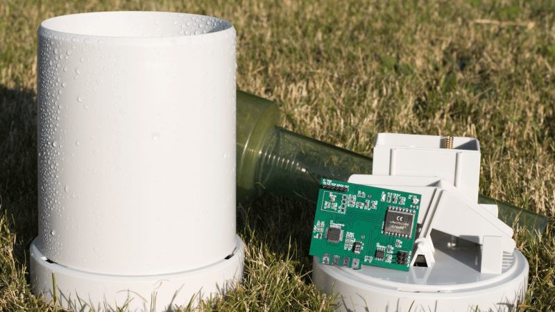
[Malte Pöggel] thinks so, and this LoRa rain gauge is the result. The build starts with a commercially available rain transmitter, easily found on the cheap as an accessory for a wireless weather station and already equipped with an ISM band transmitter. The rain-collection funnel and tipping-bucket mechanism were perfectly usable, and the space vacated by the existing circuit boards left plenty of room to play, not to mention a perfectly usable battery compartment. [Malte] used an ATmega328P microcontroller to count the tipping of the bucket, either through the original reed switch or via Hall Effect or magnetoresistive sensors. An RFM95W LoRa module takes care of connecting into [Malte]’s LoRaWAN gateway, and there’s an option to add a barometric pressure and temperature sensor, either by adding the BMP280 chip directly to the board or by adding a cheap I2C module, for those who don’t relish SMD soldering.
[Malte] put a lot of work into power optimization, and it shows. A pair of AA batteries should last at least three years, and the range is up to a kilometer—far more than the original ISM connection could have managed. Sure, this could have been accomplished with a LoRa module and some jumper wires, but this looks like a fantastic way to get your feet wet in LoRa design. You could even print your own tipping bucket collector and modify the electronics if you wanted.


Really nice work! Well organized too. Thank you!
it work with mesh?
meshtastic, reticulum etc? (no problem wifi mesh too)
Nicely done! But I would not use the BMP280 for temperature measurements. I would use a BME280 for the barometric pressure and relative humidity measurements, but add an MCP9808 for the temperature measurements. Having a setup with BME280 and MCP9808 myself, I clearly see that the MCP9808’s temperature measurements are more precise right of the bat. With the BME280 I see an offset in the temperature, which differs per device, and I think they are not temperature-calibrated. Once you know the offset, the BME280’s measurements are fine. But if the MCP9808 is already properly calibrated, why should I bother calibrating the BME280?
A very nicely done project, including the data logs and charts. It seems to have 80mA TX peaks and maybe 15mA reading blips so I wonder if the battery life will be that long. Could not tell sleep current drain from the graph.
BME280 is OK once you realize the temp sensor is just a diode and there was an early bug in the Bosch driver that did not give it enought time to load it’s cal coefficients on power up, which causes readings to be off.