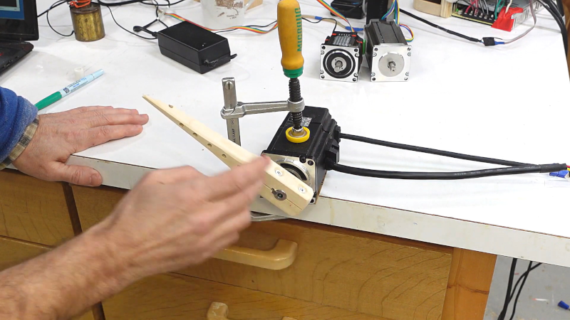
You have a project that needs something to move. Should you use a stepper motor or a servo motor? [Matthias] has an opinion, and you can hear his thoughts in the video below. One tip we’ll take away from the video: when working with motors, shoot some high-frame-rate video and slow it down to see what’s really happening.
The initial tests looked fine at normal speed. But increasing the frame rate and decreasing the playback speed showed some very interesting things like how much each motor was overshooting. The ability to control this sort of thing is a key differentiator for these kinds of motors.
In addition to a regular stepper, he also looks at a closed-loop stepper, which has some benefits and drawbacks, too, of course. The motors with the encoders were sensitive to magnetic fields, for example.
There is plenty to see in the video, but the bottom line is that your choice of motor will depend on a lot of interlocking factors including how fast you need, how much torque you require, and your desired accuracy. You could probably have guessed that but it is still very illustrative to see them on the bench and get a feel for just how these motors work and how to solve some common issues with them.
If you want to learn more about stepper motors, you are on the right site. Servos, too.


For reasons I don’t understand, even somewhat expensive servos often use brushed motors and old school resistor and wiper potentiometers. A lot of them don’t specify any particular cycle life either.
I’d be a lot more excited about servos if they’d use capsense and brushless motors!
Cost
Brushless DC motors are still relatively new in the marketplace, requiring multiple phases to be driven and some form of motor position feedback (EMF or sensored). The technology is way beyond simple DC brushed motors, and that translates to price.
I haven’t seen any brushed servos recently using resistors except for braking purposes. Most brushed servos in the past few decades have been driven via an electronic H-bridge driver, usually with tunable PID loops and feedback via optical encoders. Older drivers often used passive components to set the PID parameters in the analog domain, but newer ones do so digitally.
Many modern servo drivers are capable of driving brushed DC or brushless DC servos, and able to utilize feedback from a variety of sensors such as incremental rotary encoders (that you’d typically find on a ball screw) or absolute linear encoders (that can provide direct positional feedback on a linear axis).
The cheap Chinese iHSV servomotors are brushless and use a 1000 line optical encoder to sense position. I tested them in my 3D printer and couldn’t get achieve sufficient resolution for quality prints. But I also built them into a sand table that can run at 2000 mm/sec. It doesn’t need the precision of the steppers, and I like the speed.
There is software to tune the iHSV motors out there, but no info on what to tweak or why. In the sand table they work fine with factory default settings.
You can see what the sand table does here: https://www.youtube.com/watch?v=W_w12l8zKYc&list=PLXhpuy8MGC9zTHcek2UMJyPuZjJ8RXrlK
I gathered as much info on the iHSV motors as possible and put it here: https://drmrehorst.blogspot.com/2020/04/ihsv-servomotor-information.html
Rather hard to imagine what 2000 mm is whilst reading only to have to stop slide numbers around and those exponents to realize it’s just 2 meters! Makes for great ad copy to sell the idea of big but confusion to all of us students in life. No wonder some hate metric, in the old English system this trick won’t play. 999 if it’s any bigger there is a exponent word that is more appropriate.
@echodelta: I must be getting whooshed. “if there’s a number larger than 999 there’s an exponent word” – do you… “kilo”meters? “milli”meters?
I’m guessing the writer didn’t change units because the world of 3D printing basically works in mm, so if you compare that solution to other solutions in that application you don’t need to convert around.
Also: I can take 2000mm/sec, slide the decimal over 3 places and get a comparison to walking speed (about twice walking speed for me, I’m ballpark 1m/sec), then if I want that on a car odometer it’s 26060, then slide the decimal point back three places. Not as easy, but 7.2 km/hr.
Now do US Customary. To get a comparable speed to calculate with for this example, a meter is about a yard, so about… 72 inches/sec. Convert to ft/sec by dividing by 12, which is only easy because we memorized so many of them, we have 6 ft/sec. Now to see it on your speedometer: 66060/5280. Ugh, miles.
mm/s is the natural units in my CNC control software, and in the Gcode that I specify for the machine.
If you wrote “2 m/s” I would have to convert it back out the other way. :)
A 1000 count encoder on a typical 20 tooth GT2 pulley (2mm pitch) would give a 0.04mm resolution. ((20*2mm)/1000). That isn’t really good enough for most 3D printing, but isn’t far off. If you could gear down 1:8 using intermediate pulleys then you would get to 0.005mm which would be fine, and not too difficult to achieve.
My CNC mill uses 50K count encoders on its ball screws. With a 0.2″ pitch on the screws it could theoretically achieve 4 microinches (0.1016um) resolution, but the current software limits it to 0.0002″. The ball screws themselves are P5 which are “only” accurate to 23um error in 300mm anyway so using such a resolution would be pointless.
I have a couple of fun Schneeberger linear rails with built in encoders with a 0.5um resolution. I’m trying to decide what to build with them. I’m leaning towards a laser cutter for a few reasons: They are 8mm rails so not really suitable to heavy machining, although I could use one purely as a linear scale on an axis with 2 beefier rails providing stiffness. I think they’d be totally wasted on a plastic FDM 3D printer. I also only have two of them, so a 2D machine would be ideal unless I wanted to find a third. A laser cutter/engraver could probably make the best use of their resolution in XY as I don’t really have much use for a photolithography machine.
I thought brushless DC and stepper motors were basically the same thing. What am I missing?
In general, steppers use steel rotors, BLDC use permanent magnet rotors.
The components that go into a BLDC driver vs a stepper driver are identical, their method of control is completely different.
BLDC also tend to be 3-phase while steppers are 2-phase motors.
BLDC has rudimentary position sensing by Hall sensor feedback, or it uses the third phase winding as an inductive pickup to figure it out in the “sensorless” configuration. The controller is often a cascaded PID controller, which can be commanded to servo the motor around using position, speed, or torque control – or it may be just a dumb sequencer that simply switches the motor phases on and off to mimic a regular DC motor.
Steppers are synchronous motors, and operate under open loop control as such, so the controller has no feedback and no knowledge of how the motor is running.
About 30 years ago I added steppers to a Unimat lathe for a degree of CNC control. The setup was driven by a TRS80 model100. The problem was that traversing was far too slow and the small steppers could get out of synch if overloaded even a little. I decided to address the issue by adding servo motors with optical encoders rather than replacing the steppers. This gave the best of both worlds. So, it was not a question of either/or. I had some issues driving the servo motors as suitable semiconductors were rare back then. Also, the software was very limited, but it would seem that today you could very easily add a brushless motor to a stepper with an encoder to achieve speed, torque and precision.